4-
2
4.2 Menu Navigation
The following paragraphs explain the navigation of the various menus contained in the firmware of the
Tracker 2700 and 2700S.
For a single-page menu breakdown chart, please refer to the Quick Reference sheet supplied on your
Tracker 2700 CD.
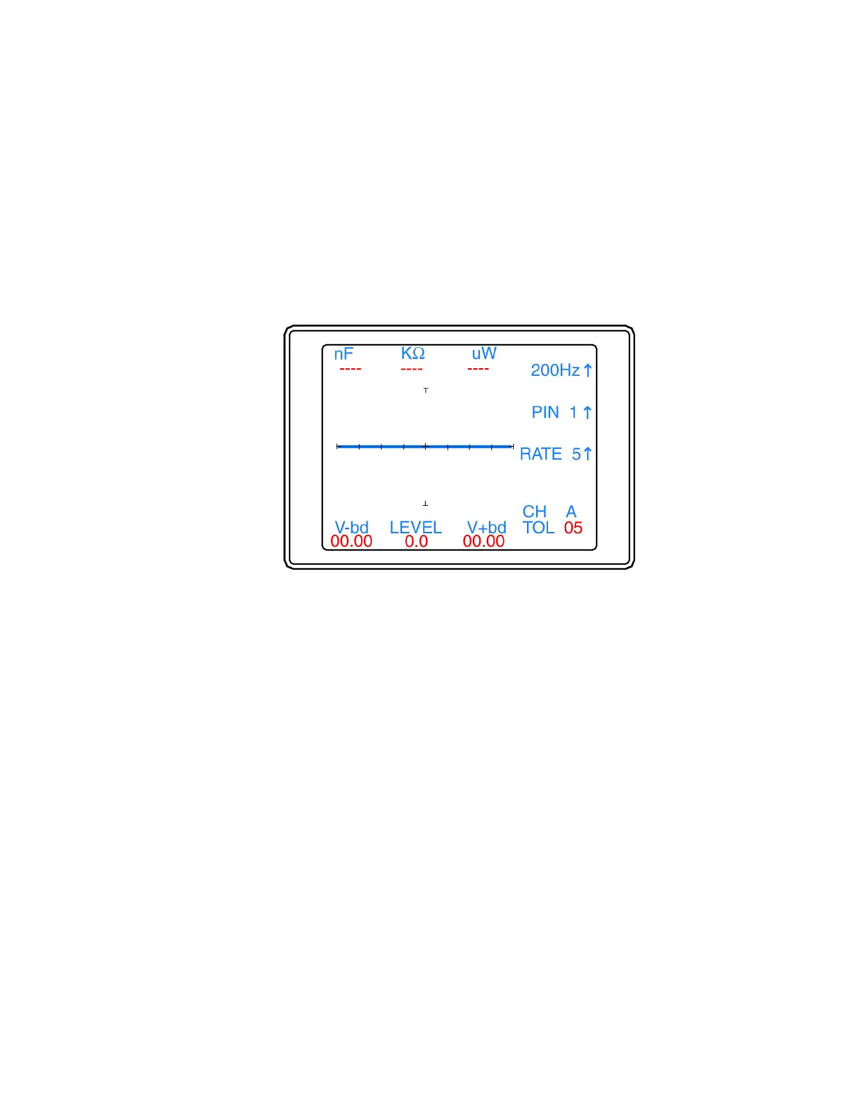
4.3 Power-Up Menu
This menu contains the range frequency (top LCD button) selection, the pin number selection (Tracker
2700S) and the alt/scan rate adjustment (bottom LCD button). Figure 4.2 shows the main menu.
Figure 4-2. Power-up Menu.
Five frequencies can be selected by pressing the top LCD Button. 20Hz, 50Hz, 60Hz, 200Hz, and 2000Hz.
Continue to press this button until the desired frequency setting is displayed on the LCD. The value is
stored in memory until changed.
The middle LCD button is used to increment the scanner pin number for Tracker 2700S. The pin number
will increment one pin position each time the middle button is pressed until the maximum number of pins is
reached (set in the Scan Package menu; see section 4.4) and then return to pin 00. Pressing the PIN button
will also stop the Scan function on the Tracker 2700S.
The bottom LCD button in this menu (labeled Rate) is used to adjust the switching frequency of the
alternation and scan modes. The rate values are numbered from 1 to 9. This number indicates the number
of times the signature will be updated before the setting switches. Continue to press this button until the
desired switching rate is reached. Scan and/or Alt button must be pressed to see results of this change. The
value is stored in memory until changed.
The other items you will see on the main menu screen are the channel (CH A or B), the compare tolerance
(TOL 05), and the DC Voltage Source level (LEVEL 0.0) and the numeric SigAssist™ values (see section
4.5).
 Loading...