4-
9
Figure 4-11. Control/Switch/Range menu
The functions of the Control/Switch/Range menu are as follows:
• 10Ω↑: Sets the resistance to be selected when the foot switch is pressed. This setting is stored in
memory until changed.
• 200mV↑: Sets the voltage to be selected when the foot switch is pressed. This setting is stored in
memory until changed.
• 20Hz↑: Sets the frequency to be selected when the foot switch is pressed. This setting is stored in
memory until changed.
• Menu button: Press the Menu button to return to the Switch menu.
Note: Safe Tracker Active Ranging (STAR) is in effect when configuring range combinations (see section
3-7).
The Control/Diags menu
The Control/Diags menu (figure 4-12) is display by pressing the Diags button in the Control menu.
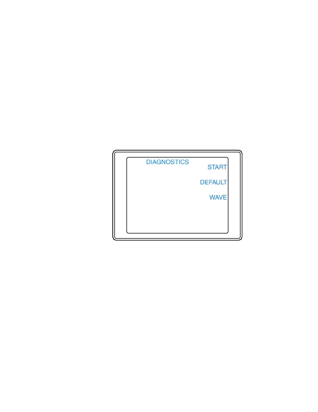
Figure 4-12. Control/Diags menu
The functions of the Control/Diags menu are as follows:
• START: Starts the Diagnostics that checks the Tracker 2700 LEDs, power supplies, and waveform
offsets. It also will adjust the waveform offsets and perform loop compensation. If a test fails, select
the corresponding button for PROCEED or CANCEL. Restart the Tracker 2700 after running
diagnostics.
• DEFAULT: Sets all user settings and the diagnostic signatures adjustments to the factory settings.
• WAVE: Toggles the display of signatures or waveforms (the horizontal and vertical waveforms used to
create a signature).
• Menu button: Press the Menu button to return to the Control menu.
NOTE: Huntron recommends the diagnostics routines not be interrupted by pressing the CANCEL button
or powering off the unit. Doing so could cause incorrect setup information to be stored in the unit memory.
However, if this should occur, rerun the Tracker 2700 diagnostics without interruption.
 Loading...