5-
4
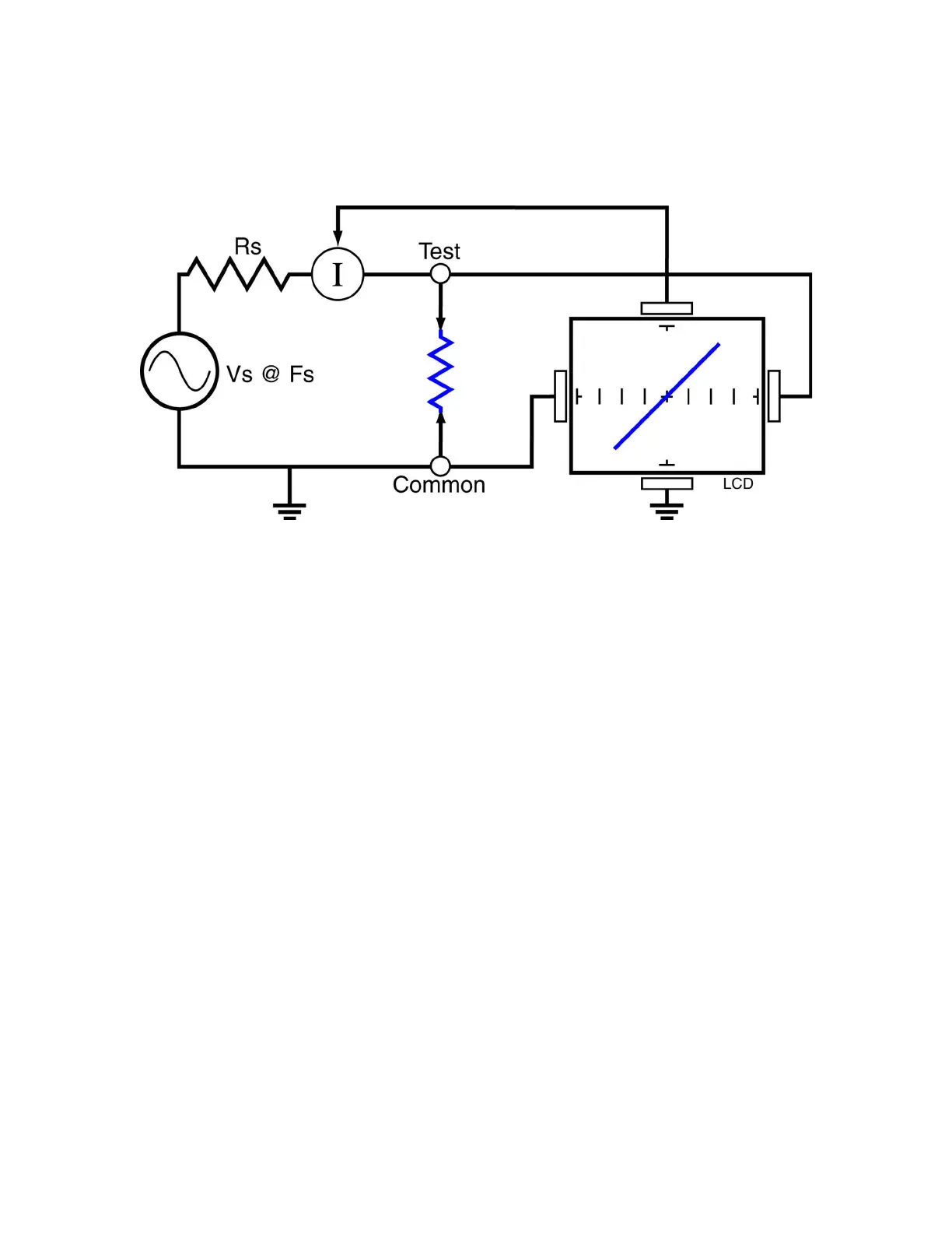
The Tracker 2700’s signature is a visual representation of Ohm’s Law in the circuit under test.
The amount of voltage applied to the circuit is shown along the horizontal axis, and the resultant
current is shown along the vertical axis. The signature is a straight line because the relationship
between voltage and current in a purely resistive circuit is linear. The slope changes as we
change the internal resistance of the Tracker 2700.
Figure 5-7. Tracker Core Circuit Block Diagram with a Resistor