5-
5
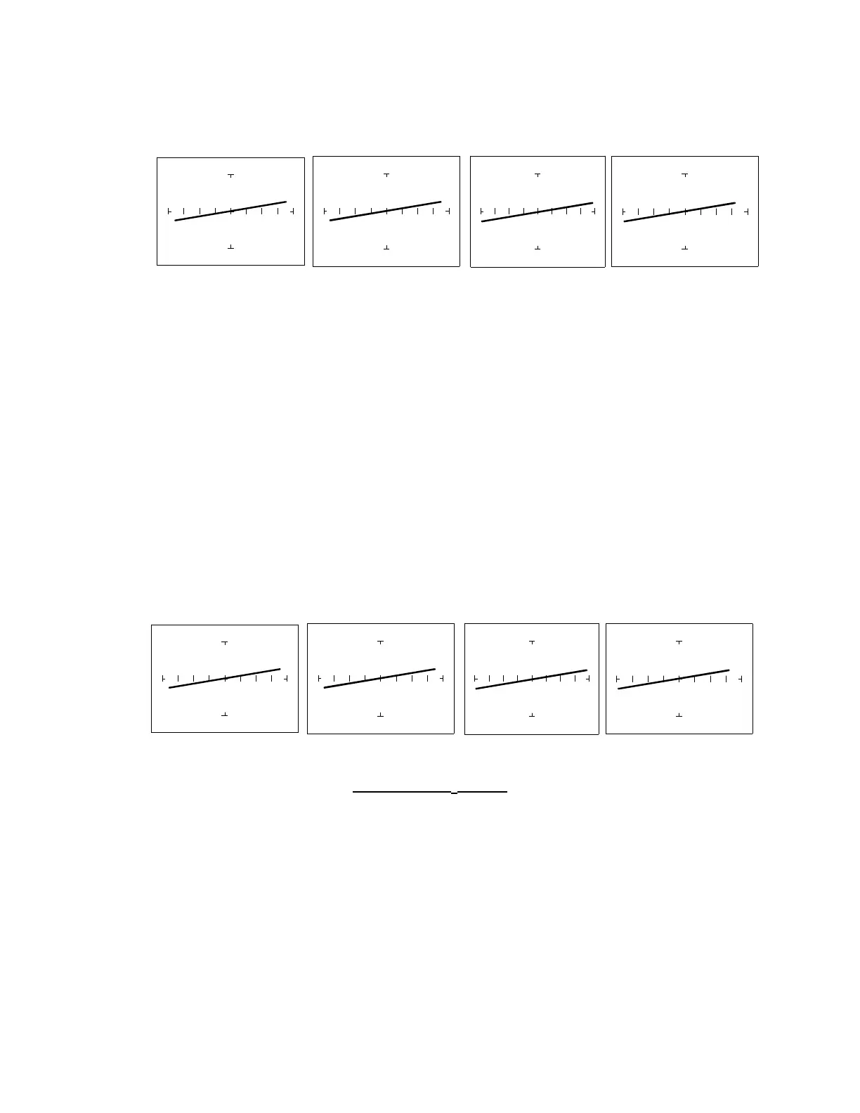
The Effect of V
S
on Resistor Tracker Signatures.
Press the 10V/5V button. The 5V range is indicated by the LED on the button being continuously
on. To select the 10V range, press this button again. Notice that the LED is now flashing on and
off.
V
S
= 10V V
S
= 5V V
S
= 3V V
S
= 200mV
100Ω
ΩΩ
Ω Range, R
L
= 150Ω
Figure 5-5. Effect of Varying V
S
on a Resistor Signature
Observe that these signatures do not change with the changing voltage. Note that when Vs is set
at 15V, the resistance range Rs automatically changes to 1kΩ. This limit on range parameter
combinations is a result of the Tracker 2700's STAR feature, it protects components from
possible excessive power (see section 3-7). In order to set V
S
to a higher voltage, you must
change R
S
to a higher value first.
The Effect of F
S
on Resistor Tracker Signatures.
In the Startup Screen, press the Frequency Select button to change the frequency of the
applied test signal. Notice that the frequency changes with each successive press of the button.
Observe that the resistor signatures in the following figures do not change as F
S
changes.
Fs = 20 Hz Fs = 50/60 Hz Fs = 200 Hz Fs =2000 Hz
100Ω Range, R
L
= 150Ω
Figure 5-6. Effect of Varying F
S
on a Resistor Signature
 Loading...