Do you have a question about the Husqvarna 115 24 05-95 and is the answer not in the manual?
Explains user rights and manufacturer obligations regarding emissions warranty.
Details the duration and scope of the manufacturer's warranty for emission parts.
Outlines owner's duties for maintaining the engine and ensuring warranty validity.
Lists conditions and actions that void the emissions warranty coverage.
Instructs users on the process for submitting a warranty claim.
Stresses the importance of reading and following all safety instructions to prevent injury.
Explains the meaning and significance of different warning symbols used in the manual.
Describes various warning labels found on the machine and their implications.
Indicates the location of the fuel tank cap for refueling.
Shows the symbol for opening the choke on the intake cup.
Indicates the symbol for stopping the engine using the throttle lever.
Advises on safe operating environments and personal condition while using the blower.
Provides guidelines for operating the blower in different environmental conditions safely.
Details critical safety measures for handling gasoline to prevent fire and burn injuries.
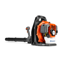
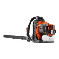
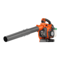
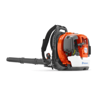
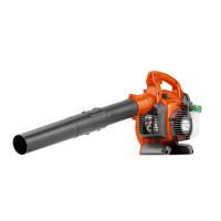
Identifies the main structural component of the blower.
Details the shoulder harness used for carrying the blower.
Locates the control for engine speed.
Locates the reservoir for gasoline.
Provides the physical size specifications of the blower unit.
Specifies the model and configuration of the engine.
Quantifies the engine's fuel usage rate.
Reports the measured sound pressure level at a distance.
Reports the sound level experienced by the operator.
Instructions for connecting the blower to the swivel joint with a hose.
Steps for installing and securing the throttle lever assembly.
Guidance on aligning and connecting blower tube sections.
Instructions for wearing and adjusting the blower's harness for safe use.
Guidance on properly placing and tightening the waist belt for comfort and safety.
Critical safety advice for handling gasoline to prevent fire and damage.
Step-by-step instructions for safely refueling the blower unit.
Instructions on how to correctly mix gasoline and oil for the 2-cycle engine.
Detailed steps for safely starting the blower's engine.
Instructions for setting the engine's idle RPM using the adjustment screw.
Procedures for safely shutting down the blower's engine.
Procedures for cleaning and maintaining the air filter for optimal engine performance.
Guidance on checking and cleaning the fuel filter to ensure proper fuel flow.
Instructions for inspecting, cleaning, and replacing the spark plug.
Procedures for checking the muffler for damage and carbon buildup.
Instructions for ensuring the air inlet is clear of obstructions.
How to check and adjust the air gap between the ignition coil and rotor.
Procedures for preparing the blower unit for long-term storage.