EasyManua.ls Logo

Husqvarna 6270 User Manual

Husqvarna 6270
184 pages
To Next Page IconTo Next Page
Page #1 background imageLoading...
Page #1 background image
Question and Answer IconNeed help?

Do you have a question about the Husqvarna 6270 and is the answer not in the manual?

Husqvarna 6270 Specifications

General IconGeneral
BrandHusqvarna
Model6270
CategorySewing Machine
LanguageEnglish

Summary

INTRODUCTION

Technical Briefing of The Viking Sewing Machine

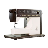
Provides a technical overview of the Viking sewing machine.

Electrical Checks and Adjustments for the 6570

Specific electrical checks and adjustments for model 6570.

Service Checks and Adjustments

General procedures for service checks and adjustments.

Electrical Wiring of Terminal Blocks and Foot Controls

Guide to wiring terminal blocks and foot controls.

STITCH FORMATION

SHUTTLE SYSTEM

BEARINGS

THREAD TENSION

UPPER THREAD TENSION

Explains how the upper thread tension device works and is adjusted.

THE DRIVING OF THE MACHINE AND ELECTRIC SPEED REGULATION

SPEED CONTROL

Discusses the main switch, foot control, and electronic speed regulation.

PATTERN MECHANISM

MOVEMENT OF THE FEED DOG

STITCH LENGTH MECHANISM

BUTTONHOLE MECHANISM

REMOVING COVERS FOR MACHINE SERIES 70, 60, 40

THE STITCH PLATE

PRESSER FOOT

THE FEED TEETH

THE SHUTTLE COVER

SHUTTLE (HOOK)

THE DRIVER

STITCH PROGRAMMERS

THE BOBBIN CASE

UPPER MAIN SHAFT

LOWER MAIN SHAFT

SHUTTLE GEARS

MOTOR

WORM WHEEL TOLERANCE

FOOT CONTROL

THE LOWEST SPEED OF THE MOTOR

SETTING THE UPPER STOP-RIGHT POSITION OF THE NEEDLE

INTRODUCTION FOR SERVICE ADJUSTMENTS

TIMING THE ZIGZAG MOVEMENT

CENTERING THE MAXIMUM ZIGZAG WIDTH

NEEDLE TO HOOK CLEARANCE

SHUTTLE TIMING

FEED DOG HEIGHT

FEED TIMING

UPPER THREAD TENSION RELEASE

SETTING THE UPPER THREAD TENSION

SETTING THE THREAD TENSION OF THE BOBBIN CASE

BUTTONHOLE COLUMN EQUALIZATION

BUTTONHOLE CUTTING SPACE

THE WORM GEAR

EXCHANGING THE FIXED CAM AND WORM WHEEL

PATTERN MECHANISM, STITCH LENGTH UNIT AND STITCH WIDTH UNIT REMOVAL

INSTALLATION OF STITCH WIDTH, STITCH LENGTH AND PATTERN MECHANISMS

REDUCTION GEAR REMOVAL AND REPLACEMENT

COMPONENT REPAIR

ASSEMBLY

WIRING DIAGRAM

EARLY MODELS CL 19 - CL 20

Wiring diagram for early model sewing machines.

CLASSES 8, 19S, 19A, 21, 21A

Wiring diagram for specific classes of sewing machines.

CLASSES 19E, 21E, 2000

Wiring diagram for classes 19E, 21E, and 2000 models.

GROUNDED (EARTHED) MACHINES

Wiring diagram for grounded machines.

FOOT CONTROL WIRING DIAGRAM

Related product manuals