Do you have a question about the Husqvarna K4000 and is the answer not in the manual?
Overview of the manual's content, purpose, and scope for maintenance and repair.
Identifies the intended audience and required knowledge level for using this manual.
Information on how product changes are communicated and integrated into manual updates.
Emphasizes the critical need to read and understand all safety instructions provided.
Highlights the importance of using specified servicing tools for maintenance procedures.
Defines severity levels for warning signals like WARNING and CAUTION.
Provides essential safety guidelines for repair and servicing personnel to follow.
Explains various safety symbols found on the product and their meanings.
Illustrates and explains symbols used within technical diagrams for clarity.
Lists and describes the specific tools required for product maintenance and repair.
Detailed breakdown and identification of components for the K4000Wetwet model.
Detailed breakdown and identification of components for the K4000Cut-n-Break model.
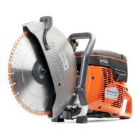
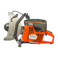
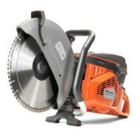
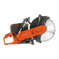
Explains the fundamental construction and shared motor unit of the K4000 models.
Information on examining, removing, and installing carbon brushes, including wear limits.
Instructions for removing and replacing the carbon brush holders.
Details on the function of the circuit board, including Softstart and Elgard features.
Explanation of the PRCD's function and testing procedures for safety.
Guidance on inspecting, testing, and handling electrical cables and connections.
Procedures for examining the rotor, including inductance testing for defects.
Instructions for removing and testing the stator for resistance and inductance.
Step-by-step guide to disassembling and reassembling the gear housing for the Wet model.
Step-by-step guide to disassembling and reassembling the gear housing for Cut-n-Break.
Procedures for removing and installing the blade guard assembly.
Detailed instructions for servicing specific components of the Cut-n-Break model.
Information on servicing the water coupling, filter, flow control, and spray nozzles.
Procedures for handling terminal bars, splices, and installing cable sleeves.
Schematic illustrating the electrical connections for the 230V model.
Schematic illustrating the electrical connections for the 120V model.
Schematic illustrating electrical connections for 120V models in UK and Ireland.
| Power source | Electric |
|---|---|
| Rated input power | 2.7 kW |
| Blade diameter | 350 mm |
| Max cutting depth | 125 mm |
| Weight | 8.5 kg |
| Vibration level front handle | 3.5 m/s² |
| Vibration level rear handle | 3.5 m/s² |
| Sound pressure level at operators ear | 95 dB(A) |
| Voltage | 230 V |