Do you have a question about the Husqvarna PW 460 and is the answer not in the manual?
Overview of the manual's purpose, including troubleshooting, repair, and testing procedures.
Information on product changes affecting service and spare parts, stressing manual updates.
Defines the intended audience as personnel with general repair knowledge of high pressure washers.
Safety guidelines for service centers and general warnings for repair personnel.
Specific safety precautions for operating the high pressure washer, including protective measures.
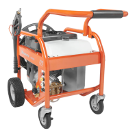
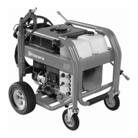
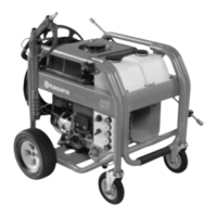
Illustrates and identifies the main parts of the product's cabinets and motor/pump unit.
Step-by-step guide for removing and reinstalling the front cabinet.
Procedure for taking apart and reassembling the switchbox and motor cover.
Instructions for removing and reassembling the pump unit.
Guide to inspecting, cleaning, and assembling the pump's bearing.
Procedure for servicing the pump head, including valve and piston handling.
Steps for disassembling the brass connector and injector from the outlet.
Procedure for removing and installing the start/stop valve and ball seat.
Detailed guide for adjusting the micro switch for optimal performance and longevity.
Instructions for lubricating and installing the nipple for hose reel replacement.
Details resistance values for motors and shows connection points for measurement.
Comprehensive guide to servicing and repairing the pressure regulation system.
Steps to verify the proper functioning of the pressure regulation system.
Procedure for removing the control piston from the pump housing.
Guide to installing the control piston and securing it correctly.
Steps to prepare the machine for checking and setting cut-off pressure.
Procedure for measuring and adjusting the cut-off pressure.
Instructions for establishing the machine's basic pressure setting.
Method for fine-tuning the machine's operating pressure.
Steps to lock and secure the adjusted pressure setting.
Presents detailed technical specifications for PW450 and PW460 models.
Lists recommended oils, lubricants, and glues for the appliance.
Specifies the recommended oil for the wobble disc housing and alternatives.
Recommends specific white greases for o-rings and sealing.
Lists recommended Loctite products for various assembly points.
Details the tools required for maintenance, including part numbers and usage.
Explains the operational states of the machine.
Describes the state when the machine is stopped and the outlet hose is empty.
Illustrates and explains the machine's operation when the gun trigger is activated.
Details the machine's standby state and the role of the breaker and S/S piston.
Shows the pressure control valve in a standby state with component labels.
Diagram showing the start-stop system with no pressure and the machine off.
Illustrates the pressure build-up process when the machine starts up.
Depicts pressure build-up, opening pressure, and micro switch activation when gun is closed.
Explains the motor stop state and the resulting standby pressure in the hose.
Shows the state when the gun is open, control piston closed, and motor starts.
Illustrates the machine running state with gun open and motor started.
Diagram showing the pressure control valve in an active state with components labeled.
Presents the electrical wiring diagram of the machine.
Provides the circuit diagram for the machine's electrical system.
This document is a workshop manual for Husqvarna high-pressure washers, specifically models PW 450 and PW 460. It provides comprehensive instructions for troubleshooting, repairing, and testing these devices, along with essential safety guidelines for personnel performing maintenance.
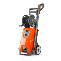
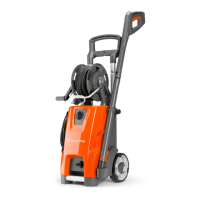
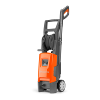
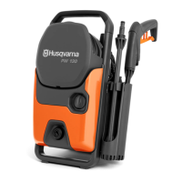
The Husqvarna PW 450 and PW 460 are high-pressure washers designed for outdoor cleaning tasks. Their primary function is to generate a high-pressure water jet for effective cleaning of various surfaces. The core of the device's operation involves a motor/pump unit that pressurizes water, which is then delivered through a high-pressure hose and a spray gun.
The machine incorporates a start/stop system that allows for automatic operation based on the spray gun's trigger. When the gun trigger is released, the system enters a "stopped" or "standby" state, where the motor pump is stopped, and the non-return valve (NRV) is closed by its spring. A ball valve is pressed against its seat by a spring, and there is no pressure from the pump. When the gun trigger is activated, the NRV opens due to pressure and flow from the pump, the ball valve is pressed against its left seat by pressure from the pump, and the motor pump starts running, delivering high-pressure water.
A pressure control valve is integral to the system, regulating the machine's pressure. In standby mode, the control piston is pushed to standby by pressure in the hose, and the spring is pressed. The breaker is activated by an activator key pressing a button, and the motor is stopped.
The system also manages pressure build-up. When the gun is closed, pressure builds up, and the micro switch is activated, indicating an "opening pressure." Conversely, when the gun is closed and the motor stops, pressure in the hose decreases to a standby pressure, which is also the pump's standby pressure. When the gun is open, the control piston is closed, the micro switch is deactivated, and the motor starts, allowing the machine to run.
The high-pressure washer is intended for outdoor cleaning. It is designed to be used with cleaning agents supplied or recommended by the manufacturer. Users should always hold the spray lance firmly with both hands during operation, as it can be affected by a thrust of up to 24.1N. The machine should not be used in environments where there is a danger of explosion, nor should it be used to clean asbestos-containing surfaces with high pressure. Operation at temperatures below 0°C is also not permitted.
The device includes a hose reel version, allowing for convenient storage and deployment of the high-pressure hose. The front cabinet and switchbox are designed for accessibility during maintenance, allowing for disassembly and reassembly.
The manual provides detailed instructions for various maintenance tasks, ensuring the longevity and proper functioning of the high-pressure washer.
General Maintenance: During servicing, it is crucial to inspect O-rings and replace them if necessary. All moving parts, sealing rings, valves, and screw threads should be thinly coated with special grease for high-pressure cleaners before assembly, with exceptions noted in specific sections.
Cabinet and Cover Disassembly/Assembly: The front cabinet can be removed by loosening specific screws, allowing access to internal components. The switchbox and motor cover can also be disassembled by removing screws and disconnecting electrical components like the motor plug, capacitor plug, and ground cable. When reassembling, it's important to fix the capacitor with a cable tie, ensuring the marking is visible and the cable tie is correctly placed. Cables and wires must be installed correctly, with the ground cable placed around the tube.
Pump Maintenance: The pump can be disassembled by removing hex screws. Maintenance on the bearing involves examining parts for damage, cleaning the D-bearing with compressed air or petrol, and replacing oil (80 ml of BP Bartran HV68 or approved alternatives like Shell Tellus T 68 or Exxon Statoil Univis N 68). The bearing parts, including thin, bearing, and thick discs, must be assembled in the correct order.
Pump Head Maintenance: The pump head can be removed from the cylinder block using a screwdriver. During assembly, the three valves must be installed correctly with their ribs in the proper position. The oil-seal and U-sleeve should be lubricated with silicone grease (Unisilkon). Pistons and O-rings are then installed, ensuring the O-ring is correctly placed around the piston before installing the thrust collar.
Brass Connector and Start/Stop Valve Maintenance: The brass connector inside the outlet and the injector can be removed using M8 and M6 pullers, respectively. The start/stop valve can be disassembled by removing the U-pin and the ball seat, which can be done without removing the motor/pump unit from the cabinet.
Micro Switch Adjustment: Adjusting the micro switch system is critical for proper operation. This involves turning the flow regulation to maximum, ensuring the product runs at high pressure, and then adjusting an M5 nut until there is a specific clearance between the key and the micro switch. The adjustment is then locked with Loctite 454.
Hose Replacement: For hose reel versions, replacing the hose involves lubricating the nipple item and then installing it into the hose reel.
Pressure Regulation Service and Repair: This involves checking the correct operation of the machine by connecting the high-pressure hose, water supply, and power cord, then pressing and releasing the spray gun trigger multiple times. The electric motor should switch on when the gun opens and switch off when closed. The control piston can be removed and installed by loosening a fastening screw and pulling out a clip.
Cut-off Pressure Check and Adjustment: After installing a new control piston, the cut-off pressure must be checked and adjusted. This involves connecting a test pressure gauge, starting the machine, opening and closing the spray gun, and reading the cut-off pressure. If the pressure is too high or low, the control piston's adjusting nut is turned to set the machine pressure in a basic setting, then fine-tuned and secured with locking paint.
Tools and Adhesives: The manual specifies recommended tools such as M6 and M8 pullers, T-handle Torx T20, T-handle Allen key 6mm, flat screwdriver, and a test manometer. Recommended glues include Loctite 680 (or 270/271) for general use, Loctite 243 (or 245) to lock the adjustment bolt at the start/stop system, and Loctite 454 for the micro switch activator arm.
This comprehensive approach to maintenance ensures that the Husqvarna PW 450 and PW 460 high-pressure washers can be effectively serviced, repaired, and kept in optimal working condition.
| Power/Max Pressure | 4600 PSI |
|---|---|
| Flow Rate/Water Flow | 4.0 GPM |
| Weight | 110 lbs |
| Dimensions | 22.5 x 21 x 35 inches |
| Hose Length | 50 feet |
| Max Pressure | 4600 PSI |
| Flow Rate | 4.0 GPM |
| Pump Type | Triplex |