22
Control Shaft & Fulcrum Ass’y (continued)
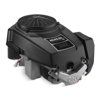
7. From the reverse side of the Upper Case; Using a 17 mm
wrench, install washer and nut to the Fulcrum. (Fig. 16)
Tightening torque: 2.5 ~ 3.3 kg–m
24.6 ~ 32.5 N–m
18 ~ 24 ft. lbs.
• To adjust the Neutral Eccentric, use a 8 mm wrench.
Fig. 16, Fulcrum Assembly
8. Mount the Hydrostatic Control Arm onto the Control
Shaft; then, align and secure with Roll Pin. (Fig. 17)
◆ On some K61 models a Snap Ring must be installed
on the Control Shaft before the OEM’s Control Lever is
installed.
Fig. 17, Hydrostatic Control Arm Assembly
To avoid possible damage to the splines of the
Pump Shaft; first, install all levers and control arms.
The driving in of the respective Roll Pins could result
in the unintentional contact with the shaft. If shaft is al-
ready present, place a protective covering over spline,
e.g., electrical tape.
Pump Shaft Assembly
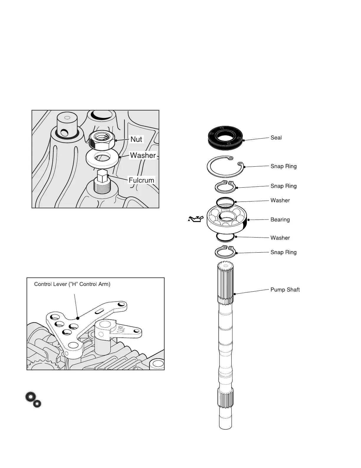
1. Install a new Bearing onto the Pump Shaft, if required.
2. Lubricate Bearing with clean oil, (old or new).
3. Installation involving a new Bearing: (Fig. 18)
• Seat Snap Ring in the Pump Shafts groove.
• Install Washer.
• Press Bearing into position.
• Install Washer.
• Seat Snap Ring in the Pump Shafts groove.
Fig. 18, Pump Shaft Assembly
 Loading...