Hussmann Corporation • Bridgeton, Missouri 63044-2483 U.S.A.
Innovator Door Installation and Service Instruction
P/N 0425683_M
15
Sequence of Operation
Normal Operation
1. Power up.
2. Heater output on for 10 sec.
3. Read Temperature and %RH.
4. Calculate % On-Time of 10 Second period.
5. Output calculated duty cycle over 10 sec-
onds.
6. Repeat Steps 3 through 5.
Failure Mode Operation
Lost or Erratic Sensor Readings
Action: 100% On
95%RH <Sensor Values <10%RH
Action: 100% On
85°F<Sensor Values < 40°F
Action: 100% On
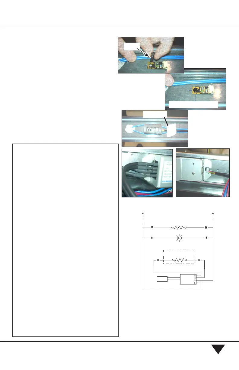
1. Remove the mullion cover between the pair of doors where
the sensor is located.
Sensor Board
2. A plastic rivet holds the sensor board securely through a
hole in one end.
Harness
3. The harness has connectors at each end. Push one end of
the harness onto the sensor board.
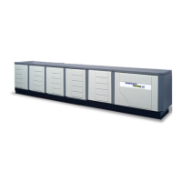
4. Position the sensor board gasket around the board and
over the harness. Route lamp wiring around the gasket.
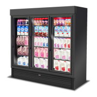
5. Important: Verify the sensor board perimeter is com-
pletely sealed. Use electrical tape to hold wiring in position
at the center of the mullion. This will avoid damage when
replacing the cover.
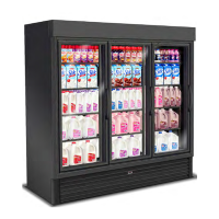
Sensor Control Box
6. The control box is mounted to the ballast tray with #8 x
3
/8 sheet metal screws.
7. Connect the sensor harness to the control box.
Door Heater Harness
8. Connect the insulated male connectors of the door heater
harness to the sensor control box. Pins are marked.
Power Connection
9. Connect the insulated male connectors for line power and
neutral to the sensor control box. Pins are marked.
Finish
10. Check that all wiring is secure within the mullion and
frame, then replace covers.
11. Restore power.
12. Verify controller is cycling the anti-condensate door
heaters.
120V Power Neutral
Frame A.S. Heaters
Calentadores A.C. de marco
Door A.S. Heaters
Calentadores A.C. de puerta
Control
Box
Humidity
Sensor
Wiring Diagram for Controller
Board Correctly Secured
Rivet
Add Tape
RefeR to Hussmann document P/n 2402799 foR moRe detail.