PN_3155541_E U.S. & Canada 1-800-922-1919 • Mexico 1-800-890-2900 • www.hussmann.com
20 ElEctrIcal / rEfrIgEratIon / controllEr
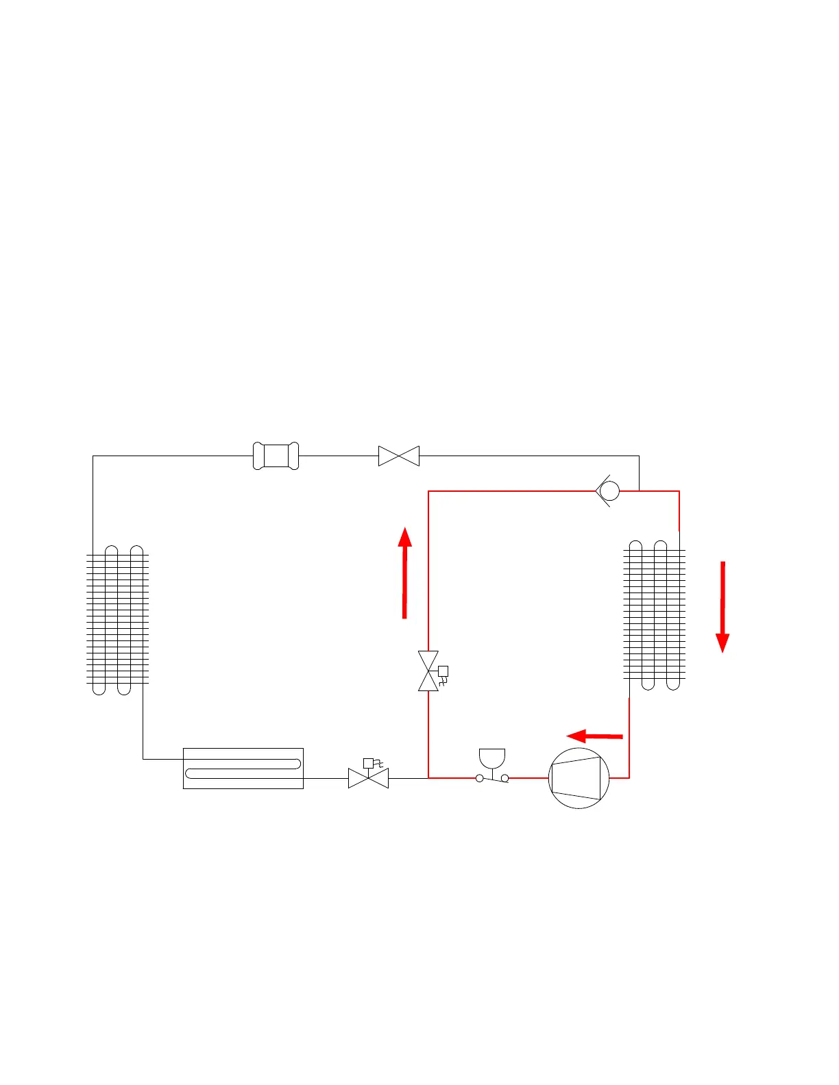
Figure C. System Diagram - Defrost Mode - Hot Gas Bypass
(This diagram is applicable for both 1 and 2-door case models)
REFRIGERATION SYSTEM
FUNCTIONALITY (Continued)
During defrost mode, the defrost solenoid
valve (HGSV) is energized and held open
allowing the gas to be redirected through the
evaporator inlet. The evaporator is split and
circuited for 2 refrigeration circuits.
Defrost cycle is temperature-terminated with
a failsafe that is 50 minutes. Normally only 3
defrost per day are required.
GDF 3.0 SHEET SIZE D
NOTES:
1. APPLICABLE STANDARDS / SPECIFICATIONS
ASME Y14.5M-1994, DIMENSIONS AND TOLERANCES
2. KEY PRODUCT CHARACTERISTICS PER EPR-0006 & IDENTIFIED WITH SYMBOL
3. MATERIAL- Error: No reference
4. REF -
K
SHEET 2 OF 2
P/N
REV
THIRD
ANGLE
PROJECTION
UNLESS OTHERWISE SPECIFIED
DIMENSIONS ARE IN INCHES.
R
FILTER
DRIER
CAP TUBE
CHECK
VALVE
EVAPORATOR
CONDENSER
CONDENSATE PAN
HGSV
RSV
COMPRESSOR
PRESSURE
SWITCH