601156_0308 17
With the engine running, engage the deck clutch switch (Fig. 3-1) and
advance engine throttle to full rpm.
NOTE: Engaging the deck clutch at high engine rpm or when under
heavy load (in tall grass for example) can cause belts and/or electric clutch to
slip, resulting in premature wear or possible damage.
Deck cutting height adjustment
Deck height is adjustable from 1-1/2”- 4-1/2” (3.81 cm - 11.43 cm) in
1/4” (.64 cm) increments. The holes in the height adjusting bar are spaced at
1/2” (1.27 cm) intervals. By turning the height adjusting stop around, 1/4”
(.64 cm) increments can be attained due to the 1/4” (.64 cm) plate that is part
of the stop. Fig. 3-10
EXAMPLE: When the height adjusting stop is placed in the 1-1/2” (3.81
cm) hole, with the 1/4” (.64 cm) plate facing to the front of the unit, the
cutting height is at 1-1/2” (3.81 cm). When the height adjusting stop is placed
in the 1-1/2” (3.81 cm) hole, with the 1/4” (.64 cm) plate on the operator’s
side of the hole, the cutting height is at 1-3/4” (4.45 cm).
The notch located at the rear of the height adjusting bar is to be used
when the deck is placed in the transport mode.
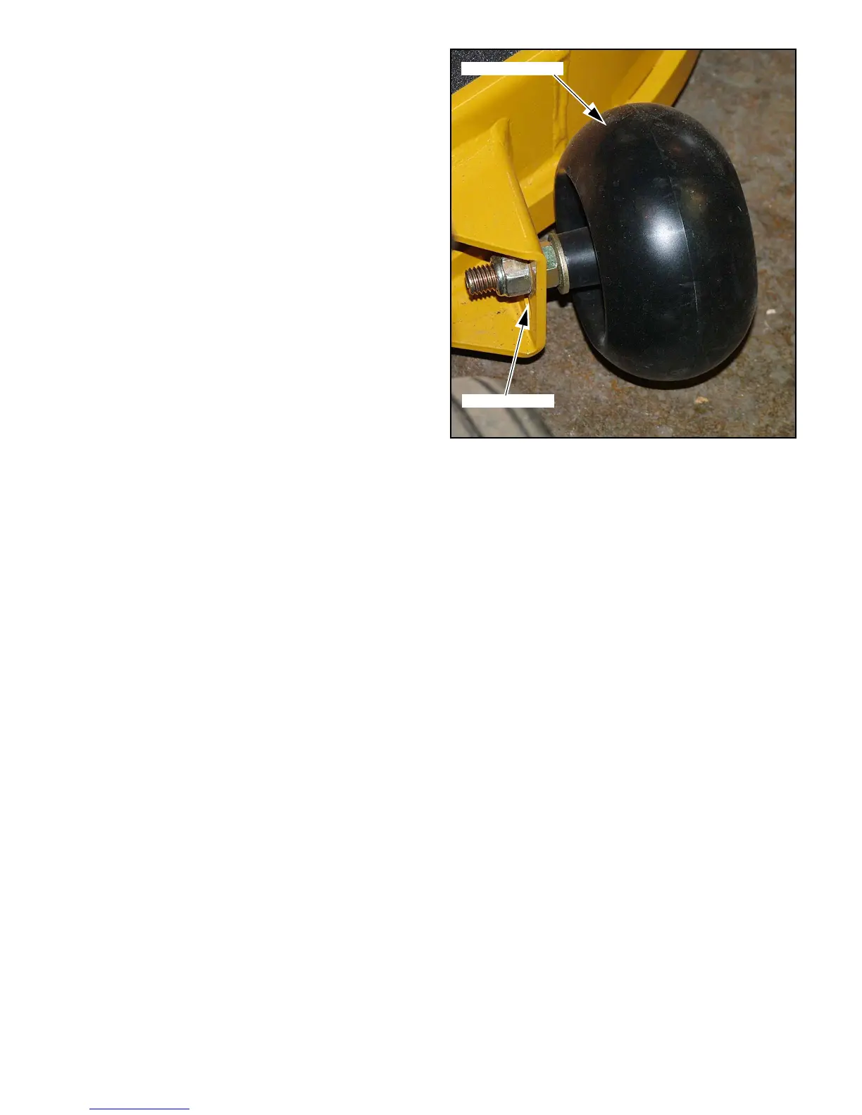
Anti-scalp wheels
Anti-scalp wheel kits are standard on FasTrak units. These anti-scalp
wheels are designed to minimize scalping when mowing on rough uneven
terrain.
After setting the cutting height, adjust the anti-scalp wheels so they
extend below the deck but do not contact the ground. They should always
be at least 1/4” to 3/4” (6.35mm to 19.05mm) below the deck. With the unit
sitting on a flat level surface, the wheel position can be adjusted up or down
as needed from 3/4” to 1-3/4” (19.05mm to 44.45mm) below the blade sur-
face. Move the wheels up or down, in 1/2” (12.70mm) increments, using the
different axle mount holes in the wheel mount bracket. Fig. 3-11
When adjusting the rear anti-scalp wheels, the wheel should be in the
same axle mount hole as the front anti-scalp wheels.
Figure 3-11
Anti-scalp wheel
Adjusting holes
 Loading...