Do you have a question about the HUSTLER 929125 and is the answer not in the manual?
Lists commonly ordered replacement parts for the Hustler Sport.
Information on available service manuals for the Hustler Sport and its engine.
Explains hardware abbreviations and provides standard torque values.
Details the procedure for installing rivet nuts on the tractor frame.
Step-by-step guide for installing the tractor battery and related components.
Explains the assembly and parts of the deck lift mechanism.
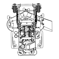
Covers the installation of the hydraulic system components.
Details the steering assembly, sub-assembly, and park brake installation.
Guide for installing 17.5 and 21 HP Briggs & Stratton engines.
Covers the installation of the fuel tank, lines, and filter.
Details the process of installing the instrument panel components.
Provides the wiring diagram for the Briggs & Stratton engine.
Explains the assembly and parts for the front wheel system.
Detailed breakdown of the front wheel assembly part number 768044.
Covers the installation of the drive wheel assembly.
Details the parts and installation of the anti-rollover wheel.
Lists parts and illustrates the assembly of the 48" deck.
Explains the pulley system for the 48" deck.
Lists parts and illustrates the assembly of the 42" deck.
Explains the pulley system for the 42" deck.
Details the components of the spindle assembly.
Guide for installing the operator's seat.
Describes the procedure for installing the mower deck onto the tractor.
Instructions for routing and tensioning belts for 48" and 42" decks.
Illustrates and lists all decals for the tractor.
Lists decals specific to the 48" side discharge deck.
Lists decals specific to the 42" side discharge deck.
Visual aids, wire harness routing, and fuel line routing guidance.
Essential safety guidelines for maintenance and adjustments.
Detailed guide for routine maintenance tasks and schedules.
Instructions for adjusting control levers, steering, belts, and more.
| Brand | HUSTLER |
|---|---|
| Model | 929125 |
| Category | Lawn Mower |
| Language | English |