Do you have a question about the Huvitz CR-7000 and is the answer not in the manual?
This document outlines the service manual for the Huvitz CR/CRK-7000 Auto Ref/Keratometer, specifically detailing the procedure for adjusting the CCD camera. This adjustment is crucial for maintaining the accuracy and functionality of the device, particularly after replacing the CCD camera or when experiencing issues with the measurement points.
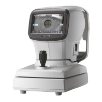
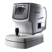
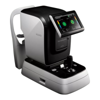
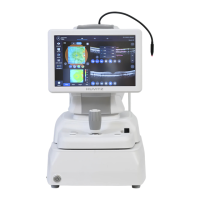
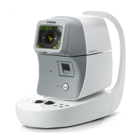
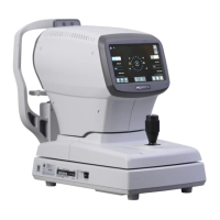
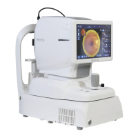
The primary function of the Huvitz CR/CRK-7000 is to perform auto refraction and keratometry, which are essential measurements in ophthalmology and optometry for determining a patient's refractive error and corneal curvature. The CCD camera plays a vital role in capturing the images necessary for these measurements.
The adjustment process begins by entering the "engineer mode" of the CRK-7000 unit. This mode provides access to various setup and calibration functions that are not typically available during normal operation. To enter this mode, the user must power on the unit and then press a specific sequence of buttons: 4→3→4→3→6→6. Once in engineer mode, the user navigates through a menu using buttons 4 and 5 to select "4. Motor test & setup," and then presses button 6 (SEL) to confirm.
After entering the engineer mode, the next step involves choosing "1. Alignment" from the menu. This is done by selecting the "1.Alignment" content and pressing the ENTER button, which is typically button 6. This selection initiates the alignment procedure for the device's optical components.
A critical step in the alignment process is to place a "REF model Eye" on the headrest. This is a standardized calibration tool used to provide a known reference for the camera and measurement system. The KEF Setup tool, which includes the REF model Eye, must be firmly fixed to the chin rest using screws to ensure stability and accurate calibration.
Once the REF model Eye is in place, the user proceeds to choose "MODE." This involves selecting the "MODE" content and pressing the MODE button, which is typically the 2nd button. This action changes the display to show an image similar to Figure 2 in the manual, which is crucial for the subsequent steps.
The user then needs to move the machine head to find the most clear position for the rings displayed on the screen. The position where the rings appear most clearly is identified as the focusing position. Once this optimal focus is achieved, the machine head must be fixed to prevent any movement during the adjustment process.
The core of the CCD camera adjustment involves manipulating the camera's physical position until the displayed picture matches the reference shown in Figure 3. This image should clearly show 6 distinct points. The adjustment is performed by pressing the 6th button, which controls the LED intensity, setting it to "LED=50." This ensures consistent illumination for accurate camera positioning.
The adjustment of the CCD camera position is a key maintenance feature designed to ensure the long-term accuracy and reliability of the CR/CRK-7000. This process involves physically adjusting the CCD camera module. The manual specifies fixing two screws, as shown in Figure 4, but emphasizes that they should not be tightened initially. This allows for slight movement of the CCD camera, which is necessary for fine-tuning its position.
During the adjustment, the user must pay close attention to the "C" and "Y" values displayed on the screen. These values are critical indicators of the camera's alignment. Other values displayed can be ignored as they are not relevant to this specific adjustment. The goal is to adjust the camera's physical position until the "C" value is either 0 or -1, and the "Y" value is within the range of 240 ± 1.
The adjustment process requires the camera to be kept in the most clear position throughout. This means continuously monitoring the image quality and ensuring the rings and points remain sharply focused while making physical adjustments to the camera.
After successfully achieving the desired "C" and "Y" values, the adjustment process is completed by saving the settings. The manual explicitly warns that if the "C" and "Y" values are not specified correctly, it will lead to "CYL measure errors," highlighting the critical importance of this calibration step.
Upon completion of the CCD camera position adjustment, the device requires "REF calibration." This indicates that adjusting the camera is one part of a broader calibration process to ensure the overall accuracy of the auto ref/keratometer. This multi-step approach to calibration and adjustment is a robust maintenance strategy to ensure the device consistently provides accurate measurements.
| Measurement Range (Axis) | 0° to 180° |
|---|---|
| Measurement Range (Pupil Distance) | 45mm to 85mm |
| Printer | Built-in thermal printer |
| Type | Auto Refractometer & Keratometer |
| Measurement Range (Spherical) | -25D to +22D |
| Minimum Pupil Diameter | 2.0mm |
| Display | color LCD |
| Power Supply | AC 100V-240V, 50/60Hz |
| Measurement Accuracy (Refraction) | ±0.25D |
| Measurement Accuracy (Keratometry) | ±0.25D |