EasyManua.ls Logo

HWH 100 Series User Manual

Default Icon
14 pages
To Next Page IconTo Next Page
Page #1 background imageLoading...
Page #1 background image
OPERATOR’S MANUAL
ML10037/MP05.0502/LHD-S
26FEB04
Four Lever Control
Hydraulic Leveling
FEATURING:
HWH CORPORATION
(On I-80, Exit 267 South)
2096 Moscow Road | Moscow, Iowa 52760
Ph: 800/321-3494 (or) 563/724-3396 | Fax: 563/724-3408
www.hwh.com
100 SERIES LEVELING SYSTEM
HWH LEVER-CONTROLLED
Straight-Acting Jacks
Suspension Air Dump
AP10037
W
CORPORATION
H
H
R
SEPARATE CONTROLS
BEFORE USING. BLOCK FRAME AND TIRES SECURELY
LR
BEFORE REMOVING TIRES OR CRAWLING UNDER VEHICLE.
STORE
EXTEND
LF
RF
CORPORATION
H
W
H
R
RR
CAUTION!
UNDERSTAND OPERATOR’S MANUAL
RR
RR
LEVELING
UNDERSTAND OPERATOR’S MANUAL BEFORE USING.
REMOVING TIRES OR CRAWLING UNDER VEHICLE.
BLOCK FRAME AND TIRES SECURELY BEFORE
CAUTION!
HYDRAULIC
5AMP
FUSE
LR
LR
WARNING
H
CORPORATION
LF
H
LF
W
LEVEL
RF
R
RF
LEVEL
OFF
DUMP
R

Other manuals for HWH 100 Series

Question and Answer IconNeed help?

Do you have a question about the HWH 100 Series and is the answer not in the manual?

HWH 100 Series Specifications

General IconGeneral
BrandHWH
Model100 Series
CategoryJacks
LanguageEnglish

Summary

HWH Lever-Controlled 100 Series Leveling System Operator's Manual

General Safety Precautions

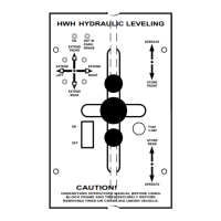
Essential safety guidelines and warnings for operating the leveling system and working around the vehicle.

Control Panel and Operation

Control Panel Identification

Detailed identification of all controls, indicators, and labels on the leveling system control panel.

Control Functions and Operations

Explanation of how to use the various controls, including levers and switches, for system operation.

Operation Procedures

Leveling Procedure Steps

Step-by-step instructions for extending jacks and leveling the vehicle correctly.

Retract Procedures

Instructions for safely retracting the leveling jacks to the store/travel position.

Maintenance and Adjustments

Level Sensing Unit Adjustment

Procedure for calibrating the level sensing unit to ensure accurate leveling.

Trouble Shooting Guide

System Diagrams and Schematics

Electrical Schematic Diagram

Comprehensive schematic showing the electrical layout and component interactions.

Related product manuals