OPERATING PROCEDURES
MP34.9901
23SEP13
AUXILIARY HAND PUMP OPERATION
The auxiliary hand pump can be used to extend or retract
the landing gear, jacks or room extensions anytime the pump
HITCHED TO THE TOW VEHICLE BEFORE OPENING
SUPPORTED BY AUXILIARY STANDS OR SECURELY
ANY VALVES.
WARNING: THE VEHICLE SHOULD BE
IMPORTANT: FOLLOW THE "SET UP" AND
"PREPARATION FOR TRAVEL" PROCEDURES
WHEN USING THE AUXILIARY HAND PUMP.
AUXILIARY
HAND PUMP
HANDLE
The auxiliary hand pump is a two stage pump that will produce
enough pressure to extend the landing gear and lift the vehicle
as well as retract the landing gear. When operating the auxiliary
pump to lift the vehicle or when the jacks are fully retracted, the
pump handle will seem to "snap" as the pump goes to the
second stage. The pumping action will be easier at first as the
second stage starts to create more pressure.
To operate the auxiliary hand pump, open the appropriate
solenoid valve. Insert the hand pump handle into the handle
receptacle and move the handle in an up and down motion.
The auxiliary hand pump may work easier if only one
valve is open at a time. Be careful to not twist the
vehicle if only one solenoid valve is open.
It is recommended to operate the auxiliary hand
pump occasionally to check it’s operation.
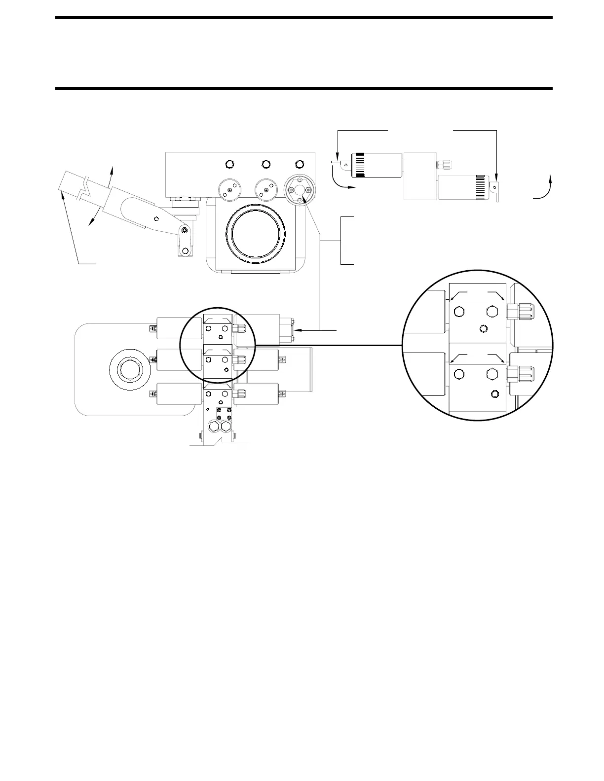
FRONT VIEW END VIEW
CLOSE
OPEN
OPERATING
MOTION
will not function.
RELEASE CAM
IMPORTANT: ONLY MOVE THE RELEASE CAM
IN THE DIRECTION SHOWN. MOVING THE CAM
IN THE OPPOSITE DIRECTION CAN DAMAGE
THE VALVES.
RET
JACK
EXT
P42088
LEFT
RET
P42089
RIGHT
EXT
JACK
EXT
B-STYLE
RET
P42091
ROOM
TOP VIEW
NOTE: If a room cannot be retracted using the
auxiliary hand pump, see "MANUAL ROOM
RETRACTION PROCEDURES".
NOTE: The hand pump will swivel to any position
which will ease the operation of the hand pump.
number of functions and the items controlled by each pair of
valves one each for the extend and retract procedures. The
NOTE: Each hydraulic function requires a pair of solenoid
solenoid valves will very for each system. The diagrams shown
on this page represent a (3) function system of (2) jacks and
(1) room as indicated by the labels shown in FIG 1. Use the
labels specific to your system when following these procedures.
FIG 1
ROOM
B-STYLE
JACK
RIGHT
EXT
RET
RET
P42089
EXT
P42091
IF A LARGE VALVE IS USED, OPEN THE VALVE
BY REMOVING THE PLASTIC PLUG THEN TURN
THE 1/4" VALVE RELEASE NUT NO MORE THAN
2 FULL TURNS COUNTER CLOCKWISE.
PLUG
PLASTIC
Room control solenoid valves may be located at the
synchronizing cylinder, not on the pump manifold.
 Loading...