EasyManua.ls Logo

Hy-Gain AR-500 User Manual

Hy-Gain AR-500
4 pages
To Next Page IconTo Next Page
Page #1 background imageLoading...
Page #1 background image
CAUTION: Read and Adhere to all IMPORTANT SAFEGUARDS listed elsewhere in this booklet. Read and observe safety,
installation and operating instructions supplied with this unit and with your antenna BEFORE installation or
operation. Retain this booklet and all instructions for your safety and future reference.
IMPORTANT SAFEGUARDS
Your antenna rotator unit, consisting of a control and a drive, has been
engineered and manufactured to assure your personal safety, but
improper installation or abuse of the unit, or the antenna connected
to it, can result in potential electrical shock or fre hazards. In order
not to defeat the safeguards incorporated in this unit, observe the
following basic rules for its installation, use and servicing.
1. Read Instructions
All the safety and operating instructions should be read before the
product is operated.
2. Retain Instructions
The safety and operating instructions should be retained for future
reference.
3. Heed Warnings
All warnings on the product and in the operating instructions
should be adhered to.
4. Follow Instructions
All operating instructions should be followed.
5. Power Lines
An outside antenna system should not be located in the vicinity of
power lines or other electric light or power circuits, or where it can
fall into such power lines or circuits. When installing an outside
antenna system, extreme care should be taken to keep from
touching such power lines or circuits as contact with them might
be fatal.
6. Outdoor Antenna Grounding
If the drive unit is installed on an outdoor antenna, be sure the
antenna system is grounded so as to provide some protection
against voltage surges and built-up static charges. Section 810
of the National Electrical Code. ANS/NFPA70, or CSA C22.1
Sections 10, 16, and 54, of the Canadian Electrical Code,
provides information with respect to proper grounding of the mast
and supporting structure, grounding of the antenna lead-in wire to
an antenna discharge unit, size of grounding conductors, location
of antenna-discharge unit, connection to grounding electrodes,
and requirements for the grounding electrode. See separate
enclosed grounding code. See FIg A.
Fig A
NEC – NATIONAL ELECTRIC CODE
Antenna Discharge Unit is not required if lead-in conductors are enclosed in a
continuous metallic shield that is permanently and effectively grounded.
Example of Antenna Grounding
According to the National Electrical Code
AR-500 Instruction Sheet
CONTENTS
Drive and Controller
Handheld Unit
2 AAA Batteries
AC Adapter
Instruction Sheet
Antenna
lead in wire
Antenna
discharge unit
Grounding
Conductors
Grounding
Clamps
Power service
ground
Grounding
Clamps
Electric
Service
Equipment
Question and Answer IconNeed help?

Do you have a question about the Hy-Gain AR-500 and is the answer not in the manual?

Hy-Gain AR-500 Specifications

General IconGeneral
BrandHy-Gain
ModelAR-500
CategoryController
LanguageEnglish

Summary

Important Safeguards

Read Instructions

All safety and operating instructions should be read before the product is operated.

Retain Instructions

The safety and operating instructions should be retained for future reference.

Heed Warnings

All warnings on the product and in the operating instructions should be adhered to.

Follow Instructions

All operating instructions should be followed.

Power Lines

Avoid locating antennas near power lines to prevent fatal electrical shock.

Outdoor Antenna Grounding

Ground outdoor antenna systems to protect against voltage surges and static charges.

Ventilation

Ensure ventilation openings are clear to prevent heat build-up and damage.

Grounding or Polarization

Use the polarized AC plug correctly; do not defeat its safety purpose.

Power Sources

Operate the control only from the specified AC power source, not DC.

Overloading

Avoid overloaded AC outlets and frayed cords to prevent shock or fire hazards.

Power Cord Protection

Protect the power cord from being rolled over or subjected to traffic.

Object and Liquid Entry

Prevent objects or liquids from entering openings to avoid shock or fire hazards.

Water and Moisture

Keep the control dry; exposure to water can cause shorts and hazards.

Cleaning

Unplug before cleaning with a slightly damp cloth; avoid aerosol sprays.

Servicing

Do not attempt to disassemble; hazards exist. Refer servicing to qualified personnel.

Damage Requiring Service

Unplug and have checked by a technician if dropped or damaged.

Replacement Parts

Use specified replacement parts; unauthorized substitutions carry risks.

Safety Check

Ensure the unit is in safe operating condition after service.

Lightning

Unplug during lightning storms or extended periods for protection.

Rooftop Installation

Use caution, wear rubber-soled shoes, and use a sturdy ladder for rooftop installations.

Rotator Installation

Determine Rotator Cable Size

Select the proper size number of rotator cable from the chart based on gauge and conductors.

Install Drive Unit

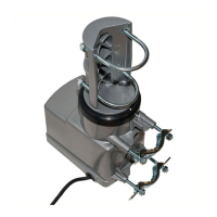
Align arrows on mast support and housing; install drive unit with arrows pointing south.

Controller Installation

Determine AC Supply Voltage

Verify country's AC supply voltage and frequency match the unit's requirements.

Connect Power Supply

Plug the power supply into the controller and household supply, observe diagnostic display.

Connect Cables

Disconnect wall plug, then connect cables between controller and drive unit.

Perform Synchronization

Reconnect AC supply, then press sync button for synchronization.

Digital Compass Operation

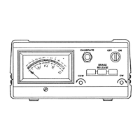
Understand the 0-360 degree display for North, East, South, and West.

Handheld Remote Setup

Install Batteries

Install 2 AAA batteries in the handheld remote for operation.

Check Operation

Press POWER button and check for HH1 in the diagnostic display.

Programming Preset Locations

Program up to 69 preset locations using UP/DOWN and memory location numbers.

Accessing a Preset Location

Access a programmed location by pressing its 2-digit number.

Displaying Memory Locations/Status

Press 99 UP to view programmed locations and system settings.

Deleting Programmed Locations

Use command 91 DOWN to delete all memory locations and reset autosync.

Synchronization

Press SYNC key or 00 DOWN to re-synchronize the control unit with the drive unit.

Auto Synchronization

Set auto sync to activate after 50 programmed moves by pressing 98 UP.

Timeout Function

Set the unit to switch off after 8 minutes of inactivity by pressing 97 UP.

Related product manuals