TH-3JRS
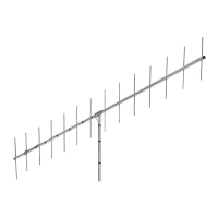
Tri-band HF 3 Elements Beam
Covers 10, 15 and 20 Meters
INSTRUCTION MANUAL
WARNING
Installation of this product near power lines
is dangerous. For your safety, follow the
installation directions.
The TH3JR-S is constructed of taper-swaged
aluminum tubing which offers low wind resis-
tance. It can be rotated with a heavy-duty TV
rotator. The light weight is ideal for rooftop or
lightweight tower installations. The antenna fea-
tures super strength stainless steel hardware and a
boom-to-mast bracket that will fit masts up to 2
inches in diameter.
General Description
The TH3JR-S antenna was designed for the Ham
who has space limitations but still wants top per-
formance on 10, 15 and 20 meters.
300 Industrial Park Road, Starkville, MS 39759
Ph: (662) 323-8538 FAX: (662) 323-6551
Specifications
Electrical
Forward Gain Up to 8 dBi
Front-To-Back Ratio 25 dB
VSWR at Resonance Less than 1.5:1
Nominal Impedance 50 ohms
Power Capability (Transmitter Output) 600 Watt PEP, 300 Watt AM
Lightning Protection DC ground
Mechanical
Net Weight 21 lbs. (11.7 kg)
Boom Length 12 ft. (3.65 m)
Longest Element 27’3” (8.30m)
Turning Radius 14’9” (4.49m)
Wind Survival 80 mph (128 kmph)
Accepts Mast 1 ¼” to 2” (32 mm to 51mm)
Surface Area 3.35 sq. ft. (0.32 sq. m)
Effective Moment* 310 ft. lb. (53 kg-m)
Wind Load at 80 MPH 87 lbs. (39.4 kg)
Hardware Stainless Steel (except for U-Bolts and some small parts)
Suitable Rotators Hy-Gain AR-40 or CD-45II
*Effective Moment is defined as the product of the antenna weight and turning radius.





 Loading...