EasyManua.ls Logo

Hy-Gain AV-14AVQ User Manual

Hy-Gain AV-14AVQ
23 pages
To Next Page IconTo Next Page
Page #1 background imageLoading...
Page #1 background image
308 Industrial Park Road
Starkville, MS 39759 USA
Ph:
(662) 323-9538 FAX: (662) 323-6551
Model AV-14AVQ
Four Bands Vertical Antenna
10, 15, 20, 40 Meter
I
NS
TR
UC
TI
ON
MA
NU
AL
General Descri
p
tion Theor
y
of O
p
eration
The Hy-Gain 14AVQ/WB-S is an omnidirec-
tional, self-supporting, vertical radiator that
operates in the 10, 15, 20, and 40 meter
amateur bands. The system will work against
earth ground or a resonant radial system when
mounted above ground. You can make your
own radial system following the manual, or
use the Hy-Gain 14RMQ Radial System Kit
available at your Hy-Gain dealer.
The antenna can be used for either Phone or
CW with either a ground or roof mount. It can
also be tuned to mid-band for use with either
Phone or CW. In either case, the SWR band
widths of the antenna are broad enough that
the antenna will operate at an SWR of 2:1 or
less from 10 to 40 meters. The 14AVQ/WB-S
is supplied with stainless steel hardware and
element clamps for all electrical and most
mechanical connections.
The use of heavy duty "Hy-Q Traps" provides
automatic band selection. The Hy-Q Traps
are parallel resonant circuits which isolate
the various sections of the antenna and give
quarter wavelength resonance on all bands.
The top hat enhances the broad-band
characteristics of the antenna and permits the
antenna to be shortened by top loading it.
WARNING
When installing your system, take'
extreme' care t o avoid any accidental
contact with'' power l i n e s or overhead
obstructions. F a i l u r e to exercise this
care could result in serious or fatal
injury.
FOR OUR OVERSEAS CUSTOMERS: The
United States used English units of measure-
ments. Please see page 12 of this manual for
assistance in identifying the hardware and
com
p
onents su
pp
lied with this
p
roduct.
Question and Answer IconNeed help?

Do you have a question about the Hy-Gain AV-14AVQ and is the answer not in the manual?

Hy-Gain AV-14AVQ Specifications

General IconGeneral
TypeVertical
Element MaterialAluminum
VSWR1.5:1
Impedance50 Ohms
Front-to-Back Ratio20 dB
PolarizationVertical
InstallationGround Mounted
Gain3.0 dBi
Power Rating1500 W PEP

Summary

General Description

Theory of Operation

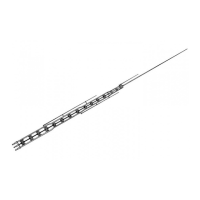
Explains the function of Hy-Q Traps and top hat for band selection.

Safety Warnings

Advises critical caution when installing near power lines.

Specifications Overview

Mechanical Specifications

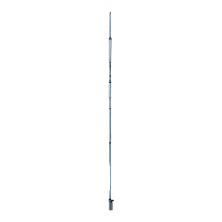
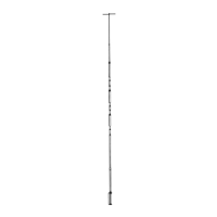
Lists overall height, mast size, wind survival, and hardware details.

Electrical Specifications

Lists frequency coverage, impedance, SWR, power capabilities, and connector type.

Site Selection and Radial System Guidance

Choosing an Antenna Site

Discusses mounting locations and ground vs. roof mounting considerations.

Radial System Installation

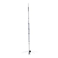
Explains radial purpose and installation for ground-mounted verticals.

Phased Vertical Antenna Concepts

Assembly and Installation Preparations

Antenna Assembly Dimensions

Tubing Clamp Installation Details

Detailed Antenna Assembly Steps

M1 and M2 Section Assembly

Connects the M1 base section with the M2 tube.

10-Meter Trap Assembly

Attaches the 10-meter trap to the M2 section of the antenna.

15-Meter Trap and M3 Section Assembly

Assembles the 15-meter trap and M3 section of the antenna.

20-Meter Trap and M4 Section Assembly

Connects the 20-meter trap and M4 section of the antenna.

M5 Section Assembly

Installs the M5 section, preparing for the top hat attachment.

Top Hat and Mounting Assembly

Top Hat Radial Assembly

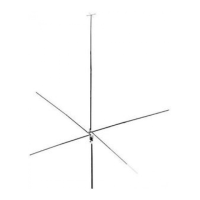
Instructions for assembling the radial top hat structure.

Antenna Mounting Procedures

Guidance on mounting the assembled antenna on a mast.

Roof Mounting and Grounding Procedures

Roof Mounting Considerations

Steps for roof mounting, including optional radial systems.

Grounding for Lightning Protection

Explains how to ground the antenna for safety against lightning strikes.

Radial RF Warning

Guying Details Using Radials

Connecting Feedline and Initial Tuning

Connecting the Coaxial Feedline

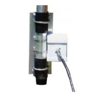
Details on connecting the feedline to the SO-239 connector and weather sealing.

Final Adjustment and Tuning Process

Guides on fine-tuning the antenna for optimal performance on each band.

VSWR Curve Adjustment for Frequency Tuning

Adjusting for Band Favoring

How to shorten or lengthen elements for frequency tuning based on VSWR.

Tuning Other Bands

Repeating the tuning process for 15, 20, and other bands.

Vertical Antenna Fundamentals

Lightning Protection Recommendation

Parts List and Component Identification

English to Metric Measurement Conversion Chart

Phased Vertical Array Engineering Report Introduction

Phased Verticals for Gain and Low Angle Radiation

Discusses benefits of phased vertical arrays for improved performance.

Hy-Gain Vertical Models Overview

Brief descriptions of related antenna models like 18HT-S and 18AVT/WB-S.

Antenna Model Specifics

Phased Array Theory of Operation

Bi-Directional Array Configuration

Describes a specific phased array setup for bi-directional patterns.

Phased Array Radiation Patterns Illustrated

End Fire Pattern Characteristics

Describes an "end fire" or bi-directional radiation pattern.

Phased Array Specifications Comparison

Cardioid Array Configuration and Operation

Cardioid Pattern Direction Control

Explains how to control the direction of the cardioid radiation pattern.

360 Cardioid Arrangement

Phased Array Electrical Specs and Phasing Lines

Multi-Banding and Radiation Pattern Considerations

Phased Array Installation, Spacing, and Components

Optional Spacing Considerations

Discusses various antenna spacings for different array types and their patterns.

Switches and Connectors for Phasing

Recommends specific types of coaxial switches and connectors for phasing setups.

Antenna Placement and Orientation

Emphasizes importance of clear surroundings and proper alignment for phased arrays.

Field Test Results for Phased Arrays

Phased Array Operation Modes and Pattern Selection

80 Meter Pattern Selection

Details pattern selection options available for the 80-meter band.

40 Meter Pattern Selection

Details pattern selection options available for the 40-meter band.

Cardioid Direction Control

Explains how to control the direction of the cardioid radiation pattern.

Radiation Patterns Chart for Phased Arrays

Related product manuals