308 Industrial Park Road
Starkville, MS 39759 USA
Ph: (662) 323-9538 FAX: (662) 323-
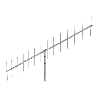
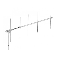
Model VB-25FM
2-Meter 5 Elements Beam
INSTRUCTION MANUAL
General Descri
tion
This antenna is a 5-element, 2-meter beam op-
timum spaced on a 75" boom. It features high
forward gain and an excellent front-to-back ratio.
The antenna is end mounted giving it the ad-
vantage of no mast decoupling and a broad
frequency response. This antenna now uses stain-
less steel hardware in most locations except for the
U-bolts. Also, this antenna now features a NEW
boom-to-mast bracket that fits up to a mast
diameter of 2 1/16 inches.
SWR and Feedline
The 25FM antenna has an input impedance of 200
ohms. The supplied balun matches the input to 50
ohms. If you are using transmission line with a
characteristic impedance other than 50 ohms or
200 ohms, a matching device must be made. Refer
to any current Amateur Handbook for information
on constructing a matching device.
Specifications
Mechanical
Boom Length 75” (1905 mm)
Longest Element 39 5/8” (1006 mm)
Net Weight 2.9 lbs (1.3 kg)
Turning Radius (Max) 73” (1854 mm)
Wind Survival 80 mph (129 kmph)
Mast Diameter 1 5/8” to 2 1/16” O.D. (41mm to 52mm)
Boom Diameter 1 ¼” O.D. (32mm)
Wind Area 0.585 sq. ft (.054 m^2) (horizontal)
0.740 sq. ft (.0688 m^2) (vertical)
Electrical
Gain (Average) 11.3 dBi (9 dBd)
Front-to-Back Ratio 20 dB
Maximum SWR 2:1
Band Width 4 MHz
Maximum Power 250 Watts continuous, 500 Watts P.E.P
Impedance 50 ohms (with balun)
Half-Power Beam Width 60 degrees (vertical polarization)
45 degrees (horizontal polarization)
Stacking Distance 82” (2083 mm) minimum