The feedline impedance is for 50 ohms (RG-
213/U). For detailed information on stacking
more than two yagis, please consult a current
Amateur Handbook.
NOTE: The boom-to-mast bracket may be
placed between the Driven Element and D1
when stackin
two antennas.
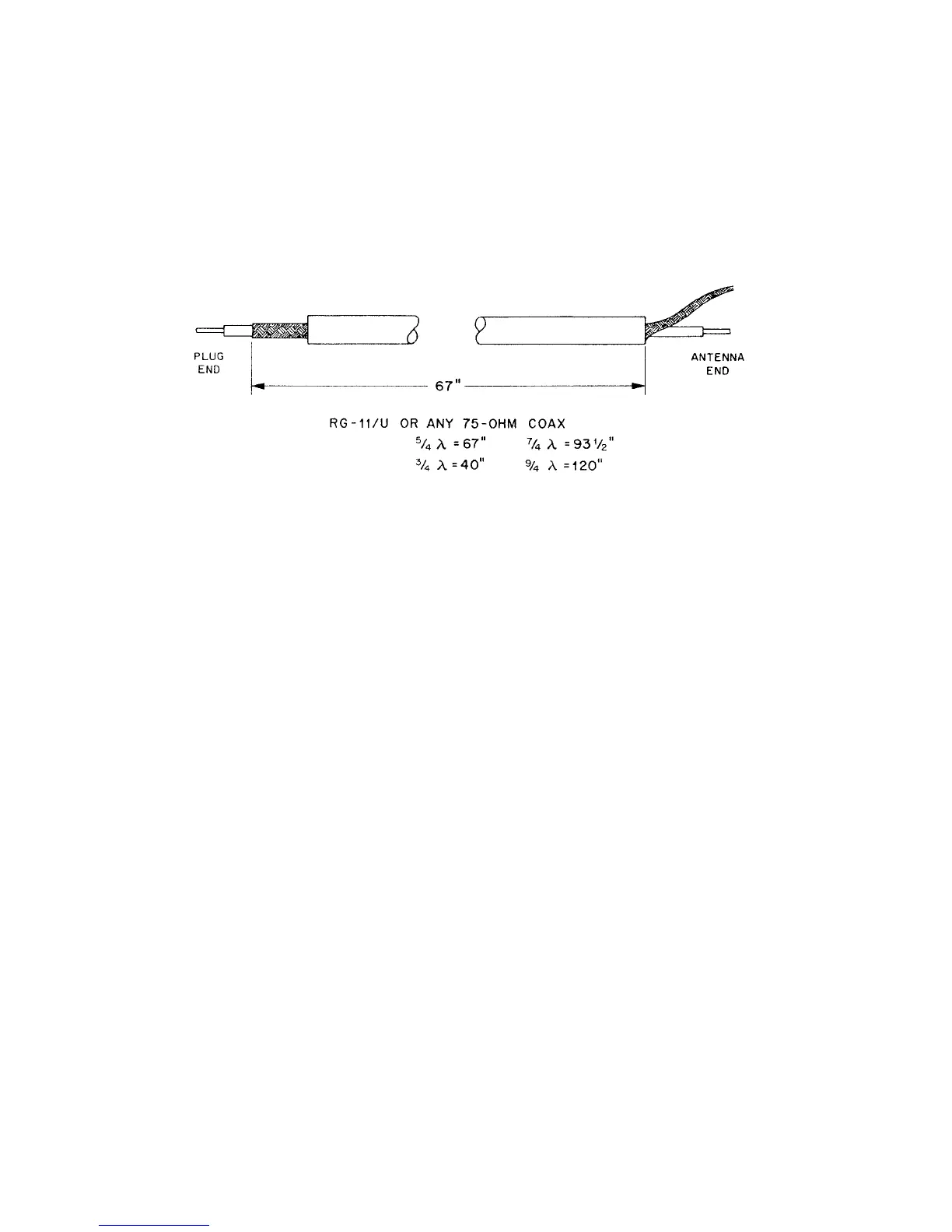
Figure 4 Phasing Line Cutting
Dimensions
Installation
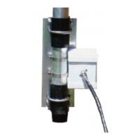
This antenna fits a 2" mast. A 2" O.D. pipe is
recommended for a sturd
mast.
Mount the antenna in the clear. Surrounding
objects-particularly power lines and other
objects of considerable mass or length-are
detrimental to the performance of the antenna.
The antenna can be mounted either vertically
or horizontally for FM or SSB/CW
respectively. Circular polarization can be
obtained by using two yagis. For information
about which polarization is best, consult local
Amateurs who use the frequencies you desire.
Step-by-Step Assembly
WARNING
Do not allow any part of the antenna to
touch power lines. This could cause
severe burns or fatal injuries.
When mounting two dissimilar antennas on the
same mast, be sure they are separated by at
least three feet
1 m
.
Remove the parts from the carton and check
them a
ainst the
arts list and the illustrations.
Select the boom-to-mast backup plate (Item
No. 5), the boom-to-mast clamp (Item No. 4)
and the four (4) 1/4"-20 x 3/4" bolts,
lockwashers and nuts (Item Nos. 16, 26, and
23).
Converting American
Measurements to Metric
1 inch (1") = 2.54 cm
1 foot
1'
= 30.48 cm
Example:
42" x 2.54 = 106.7 cm