·INSTRUCTION
MANUAL
General
Description
Installation
Instructions
ORDER NO. 500
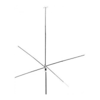
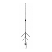
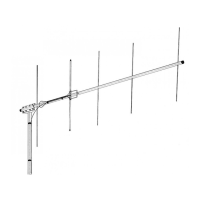
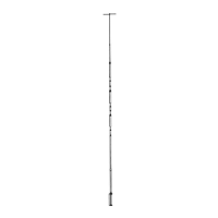
The Penetrator
The Penetratorisa full size %-wave, omnidirectional antenna. A full sized radiator with a
,lower radiation angle concentrates power closer to the ground. The antenna accepts AM,
'FM, SSB, and DSB signals, It can be fed by any standard 52-ohm coaxial cable suchas
RG-8/U and RG-58/U, For runs
over
50ft RG-8/U is recommended,
The Penetrator fits any masting material up to 1%"
aD.
A 1%" f=llumbers pipe is highly
recommended for mast use due to its low cost and high strength.
Frequency range ', 27 MHz Class
0
citizens 'band
Maximum power input .. , , : 1500\watts
Maximum VSWR , . , .. , , 1..1:1
Nominal input impedance 52-ohms
Lightning protection , DC ground
Height , 22' 9%"
Radial length ' , 8'9"
Wind (survival) , : 75 mph
Accepts mast , 1%"
0.0.
( ) Select the base assembly (item 12), the two radial plates (item 1), the M1 assembly
(item 13), and the upper insulator (item 11).
( ) Refer to Figure 1 and loosely'assemble these parts as shown, using tHe %" x 1" screws
and associated hardware. Do not tighten at this time.
NOTE: Make certain the end with %"diameter holes, 10cated3fa"from the end, are down",
and aligned with the holes in the insulator. Remember to point the two smaller holes,
(located 5%" and 13" from the bottom end) away from the base bracket These will be used
to attach the matching rod assembly.
( ) Fasten the M1 assembly to the insulator with the #10 x 13;4"screw (item 26) and
associated hardware (item 35and 41 ).Tighten securely.
( ) Referring to Figure 2, assemble the
Ya"
x 25" R1 tubes (item 3) into brackets, align the
holes and fasten with %" x 11!2"screws, nuts, and lockwashers (items 24, 34, and 40).
( ) Remove the two rod support insulators (item 21 ) and the two #10 x %" type T screws
from the parts pack and attach them to the M1 assembly as shown in Figure 3.
( ) Refer to Figure 6 and assemble the radiator tubes M2, M3, M4, the top radial assembly
and the radial elements. Refer to the compression clamp detail for their proper assembly.