Item
No.
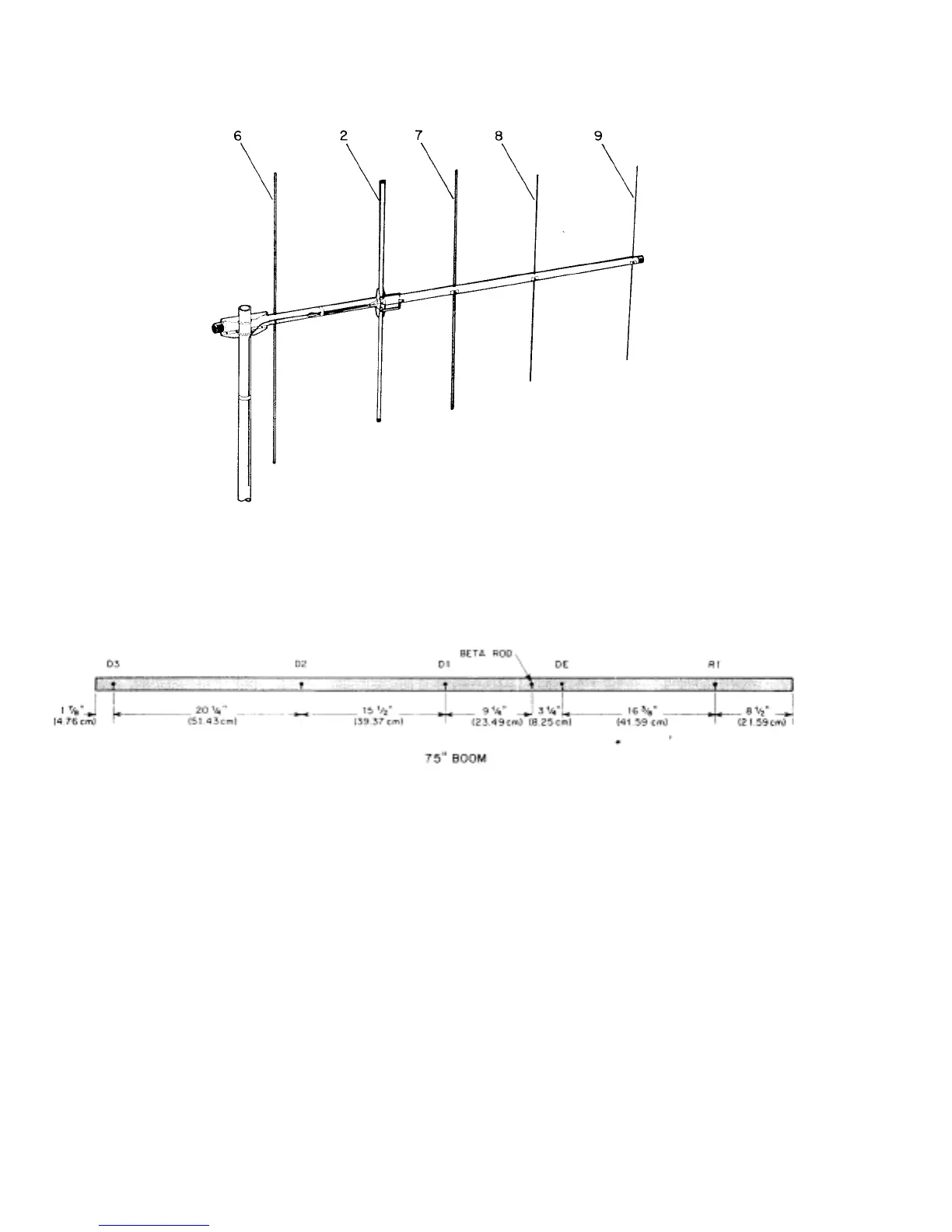
2
6
7
8
9
Description
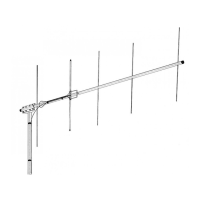
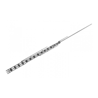
Tube, Driven Element, aluminum, 7/16" x 17 1/4"
Tube, R1, aluminum, 3/16" x 39 5/8"
Tube, D1, aluminum, 3/16" x 36 7/8"
Tube, D2, aluminum, 3/16" x 353/4"
Tube, D3, aluminum, 3/16" x 35 3/8"
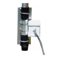
Figure 1 Overall View and
Boom Detail
Tunin
NOTE: The Driven and Parasitic Elements are
adjusted independently in the following
manner:
Parasitic Elements: This antenna is pretuned
for maximum gain and best radiation pattern
at 146 MHz. This setting will give optimum
performance over the entire 144-148 MHz
If you wish to optimize the antenna for a
frequency higher than 146 MHz, cut 1/4" off
of the total element lengths for each MHz
higher than 146.
Driven Element: SWR can be lowered to less
than 1.2:1 at a desired frequency by carefully
trimming the driven element. Keep The
element symmetrical by cutting the same
amount from each side. Typical SWR curves
are shown in Figure 2A, and a cutting chart
is shown in Figure 213. Each installation is
slightly different, so cut the driven element
for the lowest SWR at your particular
location. Measure the SWR as close to the
antenna as you can for accurate results.