ECN 04007 Manual 440-1008 Rev D Page 7 of 10
2. Drive vehicle at 10 to 15 mph.
3. Apply the brakes. If braking is too severe, adjust the gain setting down to decrease pressure, and retest. If
braking is inadequate, increase the gain setting on the in-cab electronic controller and retest.
4. Repeat this process until the brakes respond appropriately.
WARNING – The appropriate pressure setting will vary depending on the weight of the load
being transported on the trailer, weather conditions, road conditions, brake lining wear, and brake displacement.
The “TESTING AND ADJUSTMENT OF ELECTRONIC CONTROLLER UNIT”
procedure should be repeated each time the trailer is used. Failure to properly adjust the Hydrastar™ unit may
result in poor brake performance which could result in serious or fatal injuries and / or property damage.
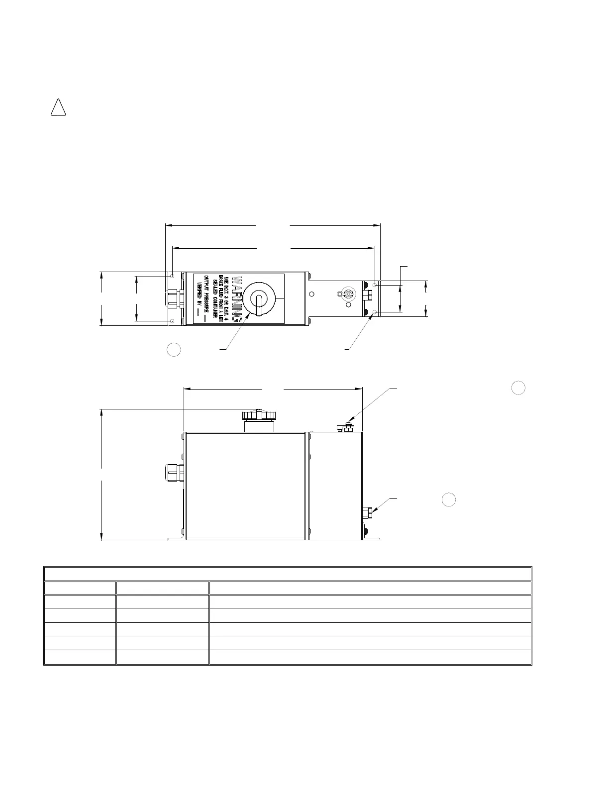
G. REPLACEMENT PARTS LIST / MOUNTING DIMENSIONS
(2.00)
4X Ø .213
MOUNTING
HOLES
1.50
(11.85)
(11.15)
2.50
(3.00)
9.84
(7.29)
FILLER
CAP
OUTPUT
PORT
3
BLEEDER / DUST CAP
2
1
OUTPUT PORT ADAPTER ASSEMBLY 3/16” INVERTED FLARE
OUTPUT PORT ADAPTER ASSEMBLY ¼” INVERTED FLARE KIT
BLEEDER VALVE / TETHERED DUST CAP KIT
 Loading...