TWO SOLENOIDS
PROPORTIONAL VALVE
Power supply Nominal : 24V
DC
(positive on contact 1) Rectified and filtered: : V
RMS
= 21 ÷ 33 (ripple max peak to peak = ± 10%)
(negative on contact 2) : 12 V
DC
(see note 4.1)
Max. power consumption 40 W
Current supplied to solenoid Imax= 2,7A type PWM square wave (with solenoid type ZO(R)-A with resistance 3,2 Ω)
Nominal reference signal (factory pre-set) 0÷10 V
DC
Reference signal variation range
(scale adjustment)
Input signal impedence Voltage signal Ri > 50 KOhm – (Ri = 250 Ω for current signal)
Potentiometers supply +5V / 10 mA at contact 3
Ramp time 10 sec. max (0÷10V of reference signal)
Electrical wirings (customer care) Shielded cable 5 pins + shield; section 0,5 to 1,0 mm
2
(20 AWG - 18 AWG)
Connections 7 contacts – terminal strip
Box format Box equipped with DIN 43650-IP65 plug; VDE 0110 wired on solenoid
Operating temperature 0 ÷ 50 °C (storage -20 ÷ + 70 °C)
Weight 190 g
Features Outputs to solenoids protected against accidental short circuits
3
MAIN CHARACTERISTICS OF E-MI-AC-01F ELECTRONIC DRIVERS
4 GENERAL SPECIFICATIONS
4.1 Power supply and wiring
The power supply must be appropriately stabilized or rectified and filtered. If the power supply is
generated by a single phase rectifier use a 10000 µF/40V capacitor; if pulse voltage is generated
by a three phase rectifier, connect a 4700 µF capacitor (see ).
Connect the reference signal to the main electronic control by means of shielded and twisted
cables. Pay attention: the negative and the positive poles must not be exchanged each other.
Shield the wirings to avoid electromagnetic noise (EMC), connecting the shield to noiseless earth
(TE), see .
It is suitable to keep the driver and its cables far from any electromagnetic radiation source (like
cables where high currents flow, electric motors, transformers, relays, solenoids, portable radio-
transmitter, etc.).
The 12 V
DC electric voltage supply is allowed only after evaluation of the performances required
from the proportional valves, and however after check with our technical office.
4.2 Reference signal, see .
The electronic driver is designed to receive a voltage reference signal according to the following
options:
– potentiometers mounted externally and wired according to the application diagrams.
– external reference signals generated by PLC, see .
– voltage from 0 to 10V
– current from 0 to 20 mA (only with option /RR).
4.3 Monitor signal
This voltage output signal allows to measure the current supplied to the coil, read by a voltmeter
between the test point M and pin 2 (see ).
Reading scale is 1 mV = 10 mA (ex.: if the voltage signal is 70 mV, coil current is 700 mA).
To visualize the signals use voltmeters with impedance >10 KΩ.
4.4 Set code
Basic calibration of the electronic driver is factory pre-set, according to the proportional valve it
has to be coupled with. These pre-calibrations are identified by a standard number in the model
code as follows:
1 = RZGO (KZGO) 2 = RZMO, AG*ZO, LI*ZO
3 = DHZO, DKZOR 4 = DPZO-A-*5
6 = QV*ZO(R), LEQZO
4.5 Calibrations available to the user, see
, , ,
.
Scale
The relation between driving current and reference signal can be regulated with the Scale adjust-
ment.
Bias (dead band)
Regulation of dead band adjusts the hydraulic zero of the valve (starting position adjustment) to
the corresponding electrical zero. The electronic card is factory pre-set for the valve it is coupled
with, according to the set code (see section 4.4). An output current is obtained when the input vol-
tage is 100 mV or greater.
Ramps see , .
The internal ramp generator circuit converts a step input signal into a slowly increasing output
signal (solenoid current).
The rise/fall time of the current is set via internal potentiometer P1 up to a max. time of 10 sec. for
0-10V of reference signal. The option /RR provides dissimmetrical ramps, ramp up is set via P1
potentiometer and ramp down is set via P2.
Dither
With the /RR option the dither frequency adjust is allowed from 100 Hz to 500 Hz.
13
9
11
5
11
11987
7 9
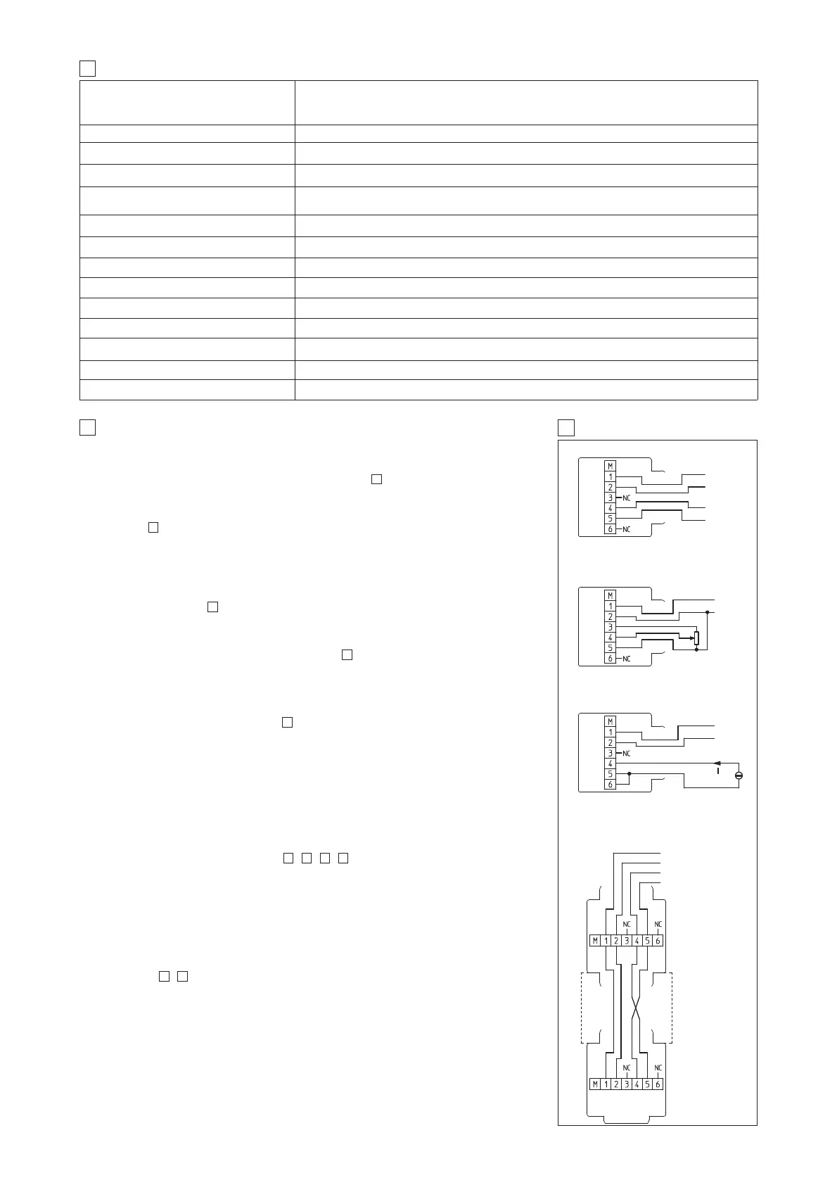
5 EXTERNAL REFERENCE SIGNALS
EXTERNAL GENERATOR VOLTAGE SIGNAL
EXTERNAL POTENTIOMETER CONNECTION
POTENTIOMETER
0 ÷ 10V (0 ÷5 Vmin) – (0÷20 mA for current signal)
+
–
EXTERNAL GENERATOR CURRENT SIGNAL
(OPTION /RR)
CONNECTION FOR TWO SOLENOIDS
PROPORTIONAL VALVE (OPTION /7)
-10 ... +10V
E-MI-AC-01F/7
E-MI-AC-01F/7
0 ÷ 20 mA
IN +
IN –
0...10V
POWER
SUPPLY
+
–
POWER
SUPPLY
+
–
POWER
SUPPLY
+
–
POWER SUPPLY
IN +
IN –