EasyManua.ls Logo

Hydrolevel Company VXT-120 - User Manual

Hydrolevel Company VXT-120
4 pages
Print Icon
To Next Page IconTo Next Page
Loading...
Programmable
Water Feeder for
Steam Boilers
120 VAC Operating Voltage
U.S. Patent No. 6,688,329; 7,093,611;
6,926,028
LIMITED MANUFACTURER’S WARRANTY
We warrant products manufactured by Hydrolevel Company to be free from defects
in material and workmanship for a period of two years from the date of manufac-
ture or one year from the date of installation, whichever occurs first. In the event
of any claim under this warranty or otherwise with respect to our products which
is made within such period, we will, at our option, repair or replace such products
or refund the purchase price paid to us by you for such products. In no event shall
Hydrolevel Company be liable for any other loss or damage, whether direct, indi-
rect, incidental or consequential. This warranty is your EXCLUSIVE remedy and
shall be IN PLACE OF any other warranty or guarantee, express or implied, includ-
ing, without limitation, any warranty of MERCHANTABILITY or fitness for a partic-
ular purpose. This warranty may not be assigned or transferred and any unautho-
rized transfer or assignment thereof shall be void and of no force or effect.
SPECIFICATIONS
MAX AMBIENT
TEMPERATURE: 100°F
FLOW RATE: 1 GPM
MAXIMUM FEED: 10 Gallons (2 Cycles)
ELECTRICAL: 120 VAC, 60 HZ
126 Bailey Road • North Haven, CT 06473 • Phone: (203) 776-0473 • FAX: (203) 764-1711 www.hydrolevel.com
UNIVERSAL COMPATIBILITY page 2
PROGRAMMABLE FEED DELAY SETTINGS page 3
PROGRAMMABLE FEED AMOUNT SETTINGS page 3
FEED COUNTER page 4
UNDERFEED PROTECTION page 4
LOCKOUT FLOOD PROTECTION page 4
INSTALLATION
Step 2 Plumbing
The feeder can be mounted on a horizontal or vertical cold water supply line.
It must be installed with a manual by-pass valve and unions (as shown
above) for future serviceability. Arrows on the valve indicate direction of
water flow. Do not install feeder on hot water supply.
IMPORTANT: It is important to prevent any contaminants from entering the
feed valve during or any time after installation. The feeder must be installed
with non-ferrous plumbing materials only to prevent rust from contaminating
the valve. Apply pipe compound sparingly. Remove and clean the feed valve
strainer after the first feed cycle to remove any contaminants that could
have
been introduced during installation. See Service / Maintenance on page 4 for
additional information.
BLUE = QUICK-GUIDE
to frequently asked questions
WARNING To prevent electrical shock or
equipment damage, power must be off during
installation or servicing of the control. To pre-
vent serious burns, the boiler should be thor-
oughly cooled before installing or servicing
control. Only qualified personnel may install or
service the control in accordance with local
codes and ordinances. Read instructions com-
pletely before proceeding.
Step 1 Warning
The VXT can be rotated to accommodate
the orientation of the incoming water line.
To rotate, loosen the 2 mounting screws
located inside the housing (A) a quarter
turn (these screws should NOT be
removed from the housing). Rotate hous-
ing to desired position (clockwise or
counter-clockwise). Once positioned,
tighten the 2 mounting screws (A).
A
VXT-120 Instructions_ VXT-24 Instructions 3/24/21 2:05 PM Page 3

Other manuals for Hydrolevel Company VXT-120

Question and Answer IconNeed help?

Do you have a question about the Hydrolevel Company VXT-120 and is the answer not in the manual?

Summary

Installation and Setup

Initial Warning for Installation

Safety warning regarding electrical shock, burns, and proper installation procedures.

Plumbing the Water Feeder

Instructions for plumbing the water feeder, including bypass valves and unions.

Wiring Diagrams

Hydrolevel Safgard & CycleGard Wiring

Wiring diagrams for Hydrolevel Safgard and CycleGard low water cut-off models.

McDonnell & Miller PS-800 Wiring

Wiring diagrams for McDonnell & Miller PS-800 Series low water cut-off models.

Float Style Control Wiring

Wiring instructions for float style controls powering the feeder.

Honeywell Model RW-700 Wiring

Wiring diagram for Honeywell Model RW-700 Guard Ring.

Configuration Settings

Setting the Feed Delay

Explanation of the feed delay feature and how to select the desired delay setting.

Setting the Feed Amount

Instructions for setting the feed amount for probe-type and float-type cut-offs.

Attaching the Service Tag

Instructions for writing installation date on the VXT Service Tag.

Operation and Maintenance

Feed Counter Usage

Explanation of the feed counter for tracking water added and resetting it.

Makeup Water Limits

Guidelines for recommended annual makeup water limits based on IBR rating.

Service and Maintenance Schedule

Tasks required annually, every 3 years, and replacement advice after 12 years.

Troubleshooting Indicators

Explanation of LOC, ERR, and flashing counter indicators for diagnostics.

Overview

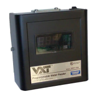
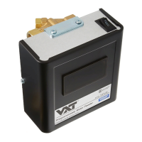
The Hydrolevel VXT Programmable Water Feeder for Steam Boilers is a sophisticated device designed to maintain optimal water levels in steam heating systems. Operating on 120 VAC, 60 HZ, it offers precise control over water feeding with a maximum ambient temperature of 100°F and a flow rate of 1 GPM. The feeder can deliver a maximum of 10 gallons per feed cycle (2 cycles) and is UL Listed, ensuring compliance with safety standards.

Function Description:

The VXT feeder's primary function is to automatically replenish water in steam boilers, preventing low water conditions that can lead to equipment damage or inefficient operation. It integrates with various low water cut-off (LWCO) controls, including Safgard, CycleGard, McDonnell & Miller, and Honeywell models, offering universal compatibility. The device features programmable feed delay and feed amount settings, allowing customization to specific boiler requirements and system conditions. A built-in feed counter records the total gallons added, aiding in maintenance and leak detection. The VXT also incorporates safety features such as underfeed protection and lockout flood protection to prevent overfilling and potential damage.

Important Technical Specifications:

  • Operating Voltage: 120 VAC, 60 HZ
  • Max Ambient Temperature: 100°F
  • Flow Rate: 1 GPM
  • Maximum Feed: 10 Gallons (2 Cycles)
  • Listings: UL Listed
  • Patents: U.S. Patent No. 6,688,329; 7,093,611; 6,926,028
  • Feed Counter Accuracy: ±15% with water pressures between 20 to 90 PSI

Usage Features:

The VXT feeder is highly adaptable and user-friendly, with several key usage features:

  • Universal Compatibility: It can be wired to various low water cut-off controls from different manufacturers, making it suitable for a wide range of boiler systems. Specific wiring diagrams are provided for Safgard Model 450 / CycleGard CG450, Safgard Model OEM-170TD, McDonnell & Miller PS-800 Series (Newer and Older Models), and Honeywell Model RW-700 Guard Ring. It also supports float-style controls, either powered by the burner circuit or a separate power source.
  • Programmable Feed Delay: Users can select a feed delay from 30 seconds to 10 minutes (factory setting is 2 minutes). This feature prevents boiler flooding by allowing sufficient time for condensate to return to the boiler before feeding. Longer delays are recommended for systems with old return lines or long horizontal runs.
  • Programmable Feed Amount: The feeder offers feed amount settings from 1 to 5 gallons, in addition to an LWCO (Low Water Cut-Off) setting (factory setting). The LWCO setting feeds only until the burner circuit re-energizes or a maximum of 5 gallons is reached, restoring boiler operation to minimum requirements. The 1-5 gallon settings ensure the feeder continues to feed until the full cycle is complete, regardless of when the LWCO is satisfied, which is useful for reaching the boiler's normal operating level. Instructions are provided for setting the feed amount based on the time it takes for water to rise to the normal operating level for both probe-type and float-type cut-offs.
  • Rotatable Housing: The feeder's housing can be rotated to accommodate the orientation of the incoming water line, providing installation flexibility.
  • Installation Flexibility: It can be mounted on either a horizontal or vertical cold water supply line and must be installed with a manual by-pass valve and unions for future serviceability. Arrows on the valve indicate the direction of water flow.
  • Diagnostic Display: A digital counter displays feed information and diagnostic codes. A small indicating light illuminates when the LWCO is calling for a feed.
    • "LOC" (Lockout Flood Protection): Appears if the feeder completes two consecutive feed cycles and the LWCO does not re-energize the burner. This indicates a potential overfill or LWCO malfunction.
    • "ERR" (Error): Appears if more than one or no delay or feed button has been selected, indicating incorrect dipswitch settings.
    • Flashing Counter: Indicates the meter has "rolled over" (exceeded 999 gallons), suggesting an excessive feed amount and potential leaks or restrictions in the makeup waterline.

Maintenance Features:

Regular maintenance is crucial for the VXT feeder's longevity and proper operation, as outlined in the manual:

  • Annual Maintenance:
    • Record the feed amount from the display onto the VXT SERVICE TAG.
    • Press the "DISPLAY RST" button on the circuit board to reset the feed counter. This helps track water usage and identify potential leaks if the feed amount exceeds recommended annual limits (e.g., 18 gallons for boilers up to 90,000 BTU/HR, up to 35 gallons for boilers 185,000 BTU/HR and higher).
    • Remove and clean the strainer located on the valve body. If the strainer shows signs of mineral deposits, a Hydrolevel Feed Valve Service Kit (Part No. 45-345) should be installed.
  • Every 3 Years: Install a Hydrolevel Feed Valve Service Kit (Part No. 45-345). If hardened calcium deposits have formed on the brass surface inside the valve, the entire valve (Part No. 45-344) should be replaced.
  • Every 12 Years: Replace the entire VXT Series Water Feeder.
  • Contaminant Prevention: It is important to prevent contaminants from entering the feed valve during or after installation. The feeder must be installed with non-ferrous plumbing materials only. Pipe compound should be applied sparingly. The feed valve strainer should be removed and cleaned after the first feed cycle to remove any contaminants introduced during installation.
  • Service Tag: A service tag is provided to record the installation date and other relevant information, to be hung in a visible location near the feeder.

Warnings and Cautions:

  • Electrical Shock/Equipment Damage: Power must be off during installation or servicing.
  • Burns: The boiler should be thoroughly cooled before installation or servicing.
  • Qualified Personnel: Only qualified personnel should install or service the control in accordance with local codes and ordinances.
  • Boiler Flooding: Improper feeder settings can lead to boiler flooding. The 1-5 gallon settings will feed the full cycle regardless of when the LWCO is satisfied, which can cause overfilling if not properly configured.
  • Water Damage Potential: Failure to maintain the feeder can lead to mineral deposits collecting in the valve, potentially causing overfilling of the heating system and water escaping into living spaces.
  • Hot Water Supply: Do not install the feeder on a hot water supply line.
  • OEM-170TD Specific Caution: When used with the Safgard Model OEM-170TD, the VXT should be set with a Feed Delay of 10 minutes and a Feed Amount of 1 to 5 gallons to prevent over-feeding and flooding. The LWCO setting should NOT be used with this model.

Hydrolevel Company VXT-120 Specifications

General IconGeneral
BrandHydrolevel Company
ModelVXT-120
CategoryControl Unit
LanguageEnglish

Related product manuals