Do you have a question about the Hydrolevel Company VXT-24 and is the answer not in the manual?
To prevent electrical shock or equipment damage, power must be off during installation or servicing. Boiler should be cooled.
Mount feeder on cold water supply line with manual by-pass valve and unions. Do not install on hot water supply.
Select the wiring diagram for the low water cut-off on the boiler. Consult boiler manufacturer's instructions for proper burner terminal connections.
Select one dipswitch for the desired feed delay to prevent boiler flooding by allowing condensate return prior to feeding.
Select one dipswitch for the desired feed amount. Boiler flooding can occur if not set properly. Use 1-5 Gallon settings for adequate water.
Write the installation date on the VXT SERVICE TAG and hang it in a visible location on or near the VXT Water Feeder.
Failure to maintain the VXT Series feeder can result in excess mineral potential for over-heating the heating element or allowing water to carry radiators into the living space.
Remove and clean the feeder strainer located on the water body. The strainer prevents contaminants from entering the feed valve.
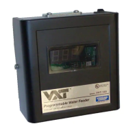
A small flashing light in the lower right hand corner of the digital feed counter indicates whenever the low water cut-off is called for.
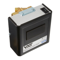
The Hydrolevel VXT-24 is a programmable water feeder designed for steam boilers, operating on a 24 VAC electrical supply. Its primary function is to automatically add water to a boiler when the water level drops below a safe operating point, preventing potential damage to the boiler and ensuring continuous operation. The device incorporates several advanced features to optimize its performance and enhance boiler safety.
One of the key usage features is its universal compatibility, allowing it to integrate with various boiler systems. The VXT-24 offers programmable feed delay settings, which are crucial for preventing boiler flooding. This feature allows condensate to return to the boiler before additional water is introduced. Users can select from multiple delay options, ranging from 30 seconds to 10 minutes, to best suit their boiler's return line conditions. For instance, older return lines or long horizontal runs might require a longer delay to ensure all condensate has returned. The factory setting is typically 2 minutes, which is sufficient for most systems with good return and vent conditions.
Another important programmable feature is the feed amount setting. The VXT-24 can be configured to feed specific amounts of water, from 1 to 5 gallons, or operate in an "LWCO" (Low Water Cut-Off) setting. In the LWCO setting, the feeder will add water only until the low water cut-off re-energizes the burner circuit, or up to a maximum of 5 gallons. This setting is designed to restore basic boiler operation. However, if the LWCO setting does not provide enough water to reach the boiler's normal operating level, users can select a specific gallon amount. This ensures that the boiler receives adequate water to maintain its optimal operating level, regardless of when the low water cut-off is satisfied. The manual provides detailed instructions for calibrating these settings based on the boiler type (probe-type or float-type cut-offs) and the time it takes for water to reach the normal operating level.
The VXT-24 also includes a built-in feed counter, which records the total number of gallons added to the boiler during automatic feed cycles or when the manual FEED button is pressed. This counter is a vital maintenance feature, as it helps track water usage and identify potential leaks in the system. Excessive feed cycles or high gallon counts can indicate issues such as leaks in the boiler or return piping, which can lead to increased oxygen levels, mineral deposits, and reduced boiler lifespan. The counter can be reset during service, allowing technicians to monitor water addition between maintenance intervals. The manual provides recommended annual makeup water limits based on the boiler's Net IBR Rating (BTU/HR), serving as a guideline for identifying potential problems.
For enhanced safety, the VXT-24 incorporates underfeed protection and lockout flood protection. The lockout flood protection feature, indicated by "LOC" on the digital counter, activates if the feeder completes two consecutive feed cycles and the low water cut-off does not re-energize the burner. This prevents continuous feeding and potential flooding. The device can be reset by briefly interrupting power to the heating system, but the manual emphasizes the importance of troubleshooting the cause of the lockout before restoring normal operation.
Installation of the VXT-24 is designed to be flexible. The feeder can be mounted on either horizontal or vertical cold water supply lines and can be rotated to accommodate the orientation of the incoming water line. It is crucial to install the feeder with a manual by-pass valve and unions for future serviceability and to prevent contaminants from entering the feed valve. The manual provides detailed wiring diagrams for various low water cut-off models, including Safgard, McDonnell & Miller, and Honeywell, ensuring compatibility with different boiler control systems.
Maintenance is critical for the VXT-24's longevity and proper functioning. The manual recommends annual maintenance, including recording and resetting the feed counter, and removing and cleaning the strainer located on the valve body. If the strainer shows signs of mineral deposits, installing a Hydrolevel Feed Valve Service Kit (Part No. 45-345) is recommended. Every three years, the Feed Valve Service Kit should be installed, and if hardened calcium deposits are present, the valve itself should be replaced. The entire VXT Series Water Feeder should be replaced after 12 years of service. These maintenance steps are essential to prevent mineral buildup, which can impede valve operation and potentially lead to overfilling or system damage.
The device also features diagnostic indicators. A small light illuminates when the low water cut-off is calling for a feed, staying on until the cut-off is satisfied. Error messages like "ERR" indicate incorrect dipswitch settings for delay or feed amounts, while a flashing counter signifies that the meter has "rolled over" (exceeded 999 gallons), suggesting excessive feed amounts and potential leaks. These indicators help users and technicians quickly identify and address issues, ensuring the safe and efficient operation of the boiler system.
| Model | VXT-24 |
|---|---|
| Category | Control Unit |
| Voltage | 24 VAC |
| Mounting | Wall Mount |
| Weight | 2 lbs |
| Input Voltage | 24 VAC |
| Enclosure Rating | NEMA 1 |
| Wiring | Terminal Block |
| Operating Temperature | 32°F to 120°F |