The CS6000B Series Operation Manual for Duplex Models provides comprehensive electrical and installation details for various Hydro-Quip spa control systems. This manual covers different heater configurations, electrical connections, circuit board settings, system operation, and troubleshooting, ensuring proper setup and maintenance of the spa equipment.
Function Description:
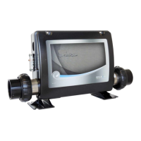
The Hydro-Quip CS6000B Series spa control systems are designed to manage the various functions of a hot tub, including heating, pumping, filtration, and lighting. These systems are available in several configurations to accommodate different installation needs and existing plumbing setups. The core function is to maintain the desired spa water temperature, circulate water for filtration, and operate accessory components like jets, blowers, and lights. The manual details how to install, configure, and operate these systems, as well as how to troubleshoot common issues.
Important Technical Specifications:
The CS6000B Series offers flexible electrical configurations, supporting both 120VAC and 240VAC power connections.
- Voltage and Amperage: The systems can operate at 120V with 16 Amps or 240V with 40-48 Amps, depending on the specific model and configuration. The heater wattage is rated at 240V, with approximately 25% output when running at 120V.
- GFCI Requirements: A Ground Fault Circuit Interrupter (GFCI) is mandatory for all portable spas and hot tubs, as specified by the National Electrical Code Article 680-42. The manual provides detailed wiring diagrams for GFCI installation in main service panels or subpanels.
- Wire Sizing: Copper conductors are required. The ground wire size should follow NEC Table 250-122, and power conductor size should follow NEC Table 310-16. A wiring chart provides minimum wire sizes for various circuit breaker ratings (e.g., 14 AWG for 15A, 4 AWG for 60A).
- Heater Flow Rate: The heater pump must provide a minimum flow of 23 GPM (Gallons Per Minute) through the heater to ensure proper operation and prevent damage.
- Temperature Range: The spa temperature can be set within a range of 80°F - 104°F (26.0°C - 40.0°C).
- Sensor Type: The system uses two interchangeable temperature sensors (SEN A and SEN B) located within the heater tube.
Usage Features:
The CS6000B Series offers several features for user convenience and system flexibility:
- Heater Configurations:
- -U Series ("Fixed" Heater): Designed for common heater positions, potentially requiring plumbing modification for alignment.
- -US Series ("Slide" Heater): Allows the heater to be positioned within 20 inches of the control for minimal plumbing modifications.
- -VH Series ("Versi-Heat" Heater): Provides a 60-inch cord for versatile installation locations, suitable when immediate equipment area space is limited. The heater must be installed horizontally on either the pressure or vacuum side of the pump.
- -LH Series ("Less Heater"): Accommodates customer-supplied custom heater configurations, with specific wiring details provided separately.
- Power Connection Modes:
- High Amp Mode (240V): Dipswitch A10 in the "off" or "down" position allows the heater to remain on when high-speed pumps or blowers are active.
- Low Amp Mode (120V): Dipswitch A10 in the "on" or "up" position turns the heater off when high-speed pumps or blowers are active.
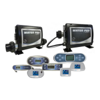
- Spa Side Control Operation: The manual details the operation of spa-side controls, including buttons for temperature adjustment, jets, blower, and light.
- Temperature: Pressing the "Temp" button displays the set temperature. Pressing it again before it stops flashing allows adjustment.
- Jets: "Jets 1" button activates pump 1, switching between low and high speeds. Low speed turns off after 4 hours, high speed after 15 minutes.
- Blower: Activates the blower, which automatically turns off after 30 minutes.
- Light: Turns the spa light on/off, with an automatic shut-off after 4 hours.
- Filtration Programming:
- The first filter cycle starts 6 minutes after power-up, the second 12 hours later.
- Filter duration is programmable for 2, 4, 6, or 8 hours, or continuous ("fc").
- For non-circulation pump systems, low-speed pump 1 and the ozone generator run during filtration.
- For 24-hour circulation systems, the circ pump and ozone generator run continuously, with potential 30-minute shutdowns in hot environments.
- All pumps and blowers briefly run at the start of each filter cycle to purge plumbing.
- Modes/Behaviors:
- Standard Mode ("St"): Maintains set temperature. Non-circ systems activate pump 1 low every 30 minutes for 2 minutes to measure water temperature.
- Economy Mode ("Ec"): Heats the spa to the set temperature only during filter cycles.
- Sleep Mode ("SL"): Heats the spa to within 20°F/10°C of the set temperature only during filter cycles.
- Modes are changed by pressing "Temp" or "Set," then "Light."
- Optional Equipment: The system supports optional accessories like the Dolphin Remote (Part Number 34-0215) and an IR Receiver (Part Number 34-0216C). The spa light circuit is LED compatible.
Maintenance Features:
The manual provides guidance for system start-up, sensor testing, and troubleshooting common issues:
- System Start-Up Sequence:
- Ensure power is off.
- Open all water shut-off valves.
- Close hose bib/drain valve (if equipped).
- Close filter nut, housing drain plug, and air relief valve (if equipped).
- Fill spa with fresh tap water to recommended level.
- Inspect plumbing for leaks.
- Close all air control valves.
- Plug in unit or turn on breaker.
- System enters "PR" (Priming Mode) and performs diagnostic checks.
- Press "Jets" repeatedly to bleed air from pumps.
- Bleed air from pressure filter (if equipped).
- Verify air blower operation (if equipped).
- Verify light operation (if equipped).
- Verify auxiliary pump operation (if equipped).
- Adjust temperature set point.
- Heater Start-Up Sequence:
- Pump runs for 2 minutes to verify sensors.
- Heater turns on for 6.5-18 seconds (heat indicator "solid").
- Heater turns off for 90 seconds to check water flow (heat indicator may "flicker").
- After flow verification, heat indicator returns to "solid," and spa heats to set temperature.
- Troubleshooting: The manual lists common problems and their solutions:
- Nothing Operates: Check main breaker, sub-panel breaker, GFCI, power switch, component plugs, power cord, and high-temperature protection.
- No, Low, or Surging Water Flow: Address air locks, restricted flow (check valves and suction fittings), dirty filters, and low water levels.
- Low Speed Pump Not Operational: Check circuit board configuration, pump plug, and blown fuse.
- Jets or Blower Not Operational: Check component plugs, blown fuse, and high-temperature protection.
- Therapy Jet Not Operational: Open shut-off valves, clean/replace filter, adjust jets/diverter valve, check for restricted flow.
- Water Leaks: Adjust water level (overfilled spa, too many people), close drain valve, tighten couplings/unions, check pump seal, plumbing connections, spa-side control, and air blower plumbing.
- No Heat: Adjust set point, check high-temperature protection, current limiting (120V systems), power, low water flow, and system mode (Economy/Sleep).
- Light Not Operational: Replace bulb, replace reflector, plug in light.
- High Heat: Adjust filter cycles, set point, and remove spa cover.
- GFCI Breaker Trips: Reset breaker after lightning/electrical storm or power surge. If immediate trips, contact technician for defective component or improper GFCI installation.
- Spa Side Messages: Explanations and required actions for various display messages like "---" (temperature unknown), "HH" (overheat at heater), "OH" (overheat at spa water), "SA"/"Sb" (sensor issues), "Sn" (sensors out of balance), "HL" (significant temperature difference/flow problem), "LF" (persistent low flow), "dr" (inadequate water detected), and "IC" (potential freeze condition).
- Testing Sensors: Provides a step-by-step guide to diagnose faulty sensors or circuit boards by swapping sensor positions.
- Warranty Information: Hydro-Quip provides a 1-year warranty on the control box for defects in material and workmanship, excluding damage from normal wear, freezing, low voltage, chemical abuse, accident, negligence, alteration, improper installation, use, or care. The purchaser is responsible for removal/reinstallation labor and freight.