18 ArcGlide THC Replacement Parts Field Service Bulletin 806560
2 – Replacing ArcGlide parts
6. Install cable connectors in the following connectors on the lifter interface board:
7. Install the connectors from the switches and LED on the front cover to the lifter interface board:
8. Replace the front cover of the motor enclosure and fasten the 4 screws. Tighten the screws to 1.13 N·m (10 lb·in.).
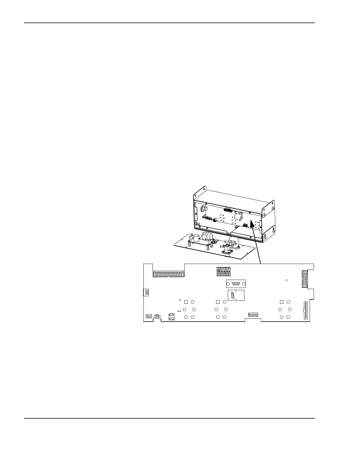
228581 – HMI processor board
Follow the steps in Accessing HMI parts on
page 12 to open the rear panel. Set aside all
screws and other hardware for reuse.
To remove the HMI processor board:
1. Remove the Ethernet cable connector from
J7 and the red and black wires to the
power source from J12.
2. Remove the 3 toggle switch boots on the
front of the enclosure.
3. Remove 6 standoffs around the processor
board.
4. Push gently on the board to remove it and
the front panel from the enclosure.
5. Remove cables from connectors J3, J4, J8, J9, J10, J11.
6. Remove the screws from the standoffs at the upper corners and the lower center of the board.
7. Remove the board from the front panel.
8. On the front of the board, remove the hex nuts and round washers from the toggle switches. Save the washers for
reuse.
J1 Upper limit switch
J3 Lower limit switch
J4 Breakaway
J6 Motor brake encoder
J7 Laser pointer
J2 LED
J8 Enable/disable switch
J9 Up/down switch