28 ArcGlide THC Replacement Parts Field Service Bulletin 806560
2 – Replacing ArcGlide parts
To remove the LCD display in the HMI, follow the steps in Accessing HMI parts on page 12 to open the rear panel of the
HMI. Set aside all screws and other hardware for reuse.
To access the LCD display, you must use the following
procedure to remove additional parts:
228581 – HMI processor board on page 18
To remove the LCD display in an HMI:
1. Remove the
ribbon cable connector from the LCD display board.
2. Remove the threaded standoff from the upper right of the board.
3. Remove the remaining 3 screws from the corners of the display board.
4. Lift the board off the standoffs.
To replace the LCD display in an HMI:
1. Fit
the new LCD display board over the standoffs with the black connector next to the green ribbon cable.
2. Replace the threaded standoff screw in the upper right. Tighten the standoff to 0.90 N·m (8 lb·in.).
3. Fasten the 3 screws in the remaining standoffs. Tighten the screws to 1.13 N·m (10 lb·in.).
4. Fasten the red and black wires to the cable tie anchor on the front of the enclosure.
5. Connect the ribbon cable to the black connector on the display board.
Use the following procedure to replace additional parts:
228581 – HMI processor board on page 18
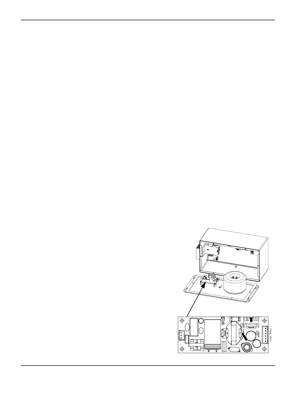
228590 – 120 VAC, 5 V, 5 amp, 25 W power source
Follow the steps in Accessing control module parts or Accessing HMI
parts on page 12 to open the rear panel of the enclosure. Set aside all
screws and other hardware for reuse.
To remove the power source:
1. Remove the cable connectors for the red and black wires to the
processor board and the black and white wires to the surge board.
2. Remove the screws from the standoffs.
3. Lift the board off the standoffs.