Diagram 9
The Installation Procedure
Hypervolt Limited, Unit 17, Innovation Business Centre, Rainham, RM13 8HZ, UK 9
Revision 1. Issue date: Feb. 2020
Make sure you perform an adequate pull test at the unit
electrical terminal to conrm the connection is acceptable.
The Hypervolt Home 2.0 incorporates an automatic
thermal based detection mechanism for poor power input
connections.
You should perform all required electrical tests at this stage.
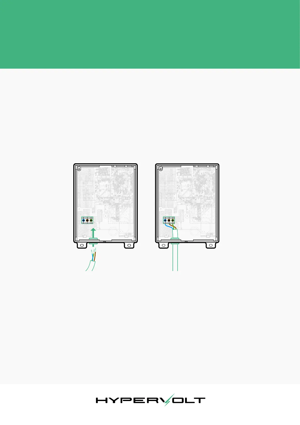
Next, proceed to make the electrical connections inside
the Hypervolt device. Refer to Diagram 9 to identify the
cable entry location and the power input connector inside
the unit. All of the cables that are to be connected into the
supply terminals should have their insulation stripped back
12-15mm and have suitable ferrules crimped over in order
to ensure the best electrical connection possible.
 Loading...