Hypnocube 4Cube Instructions v 6.5, December 2013
- 3 -
Part 1: The Good
Part one is assembling the controller PCB. This should be straightforward for anyone who has done PCB work;
there's nothing exotic here.
Estimated completion time: 1.5 - 3 hours.
We will start with the lowest-profile parts and work our way up, as that allows your working surface to hold the
parts in place while we solder the bottom. Besides that, there is no particular requirement for assembly order.
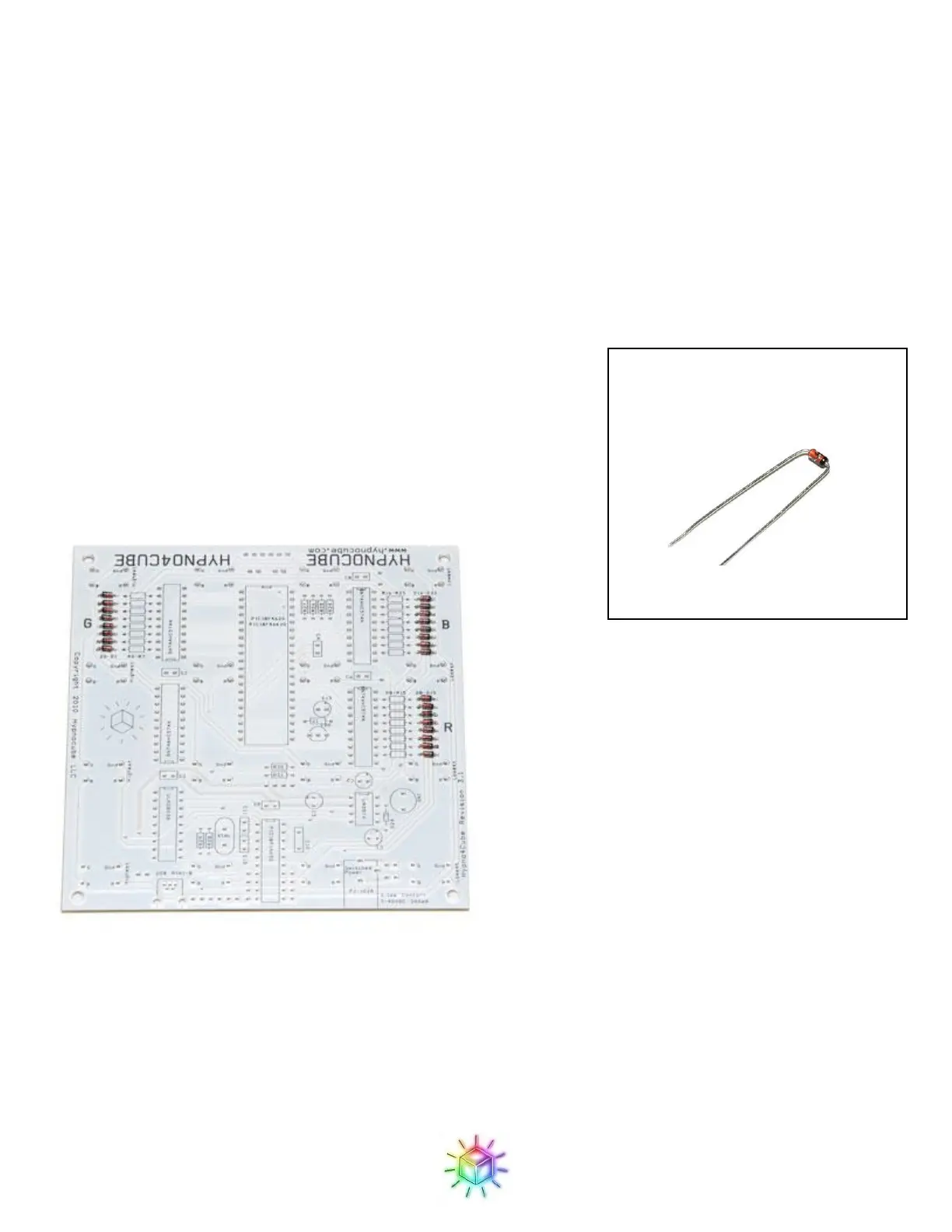
Step 1: Diodes
The first parts we will place are the 24 signal diodes. Orientation is
important here; make sure the black stripe on the diode aligns with the
stripe on the part outline. The diodes go in the three banks marked D0-
D7, D8-D15 and D16-D23.
Figure 2 shows the board with all diodes in place.
Figure 2: Diodes in place.