Hypnocube 4Cube Instructions v 6.5, December 2013
- 36 -
Step 2: Attaching the power switch
We will next connect the power switch before proceeding with the LED
planes. While they may get in the way a bit while attaching the planes,
having power available will allow us to test each plane as we go. This
will make it much easier to find and fix any problems in the LED
lattice, while it is still accessible and not surrounded by other LEDs.
First, cut the wires into approximately 6” (15 cm) lengths. You should
have 2 red wires and 4 white wires. The colors will distinguish what the
wires are used for – otherwise they’re identical 24 AWG stranded wire.
The red wires will carry power from the AC adapter and the white
wires are signal wires for the two buttons. In this step we will use only
the red to wire the power switch.
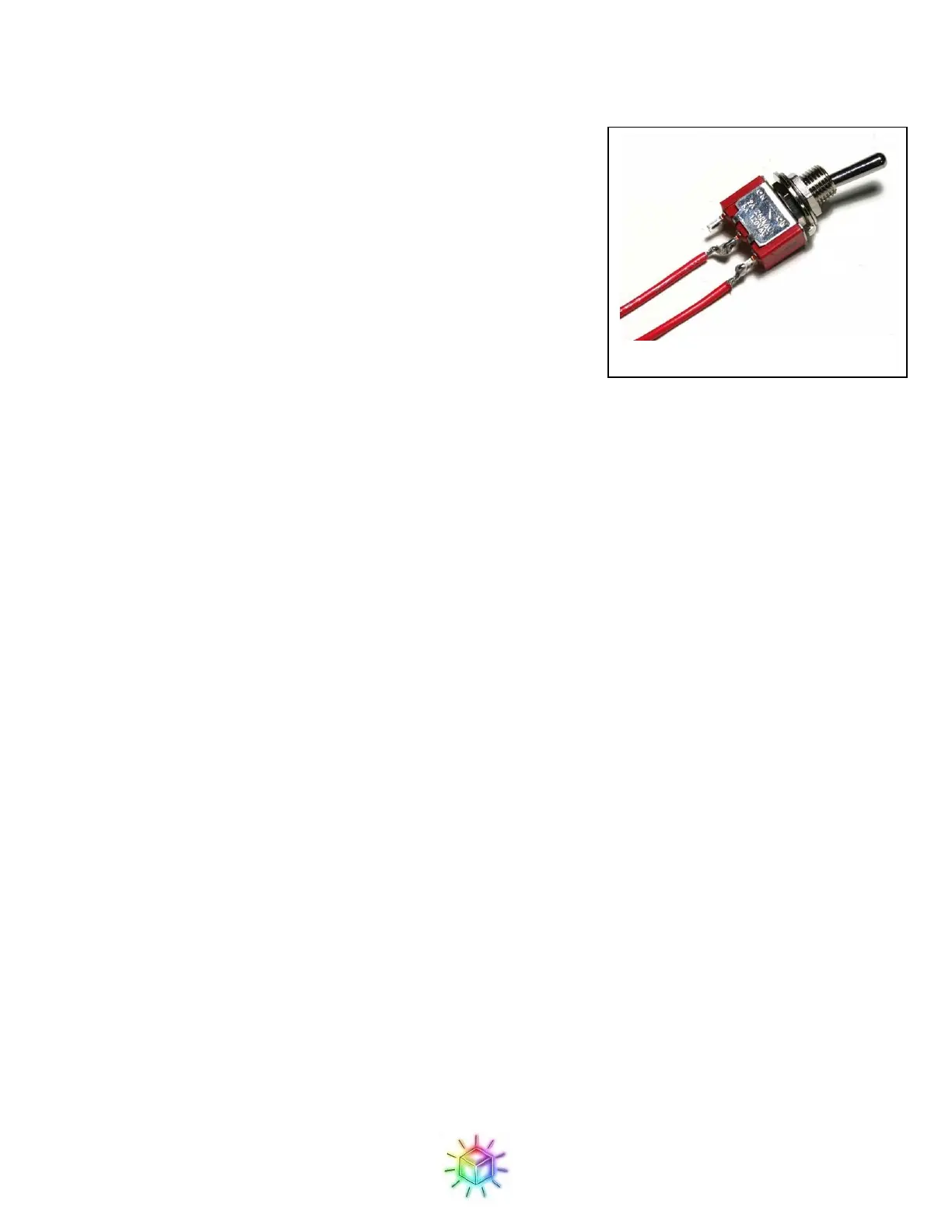
We will use two red wires for the power switch. The power switch is not polarity sensitive, so just connect one
of the wires to the middle tab and the other one to one of the side tabs. Make sure you use the ON-OFF toggle
switch, and not the (ON)-OFF momentary switch! (If the switch springs back, it’s the wrong one.)
The switch will be ON when the toggle is away from the wired side; something to keep in mind when mounting
the switch to the case later. In Figure 62: The power switch. is in the OFF position.
Figure 63 shows the connection points for the power switch on the PCB. Note that there’s a similar footprint
also labeled “PWR Switch” on the opposite side of the board, which was for the regulator circuit which was
deprecated when we moved to USB power. The one you want is the one by the USB plug, as shown below.
Tinning the wire can help if you have difficulty getting the stranded wire cleanly through the holes. Once in
place, you’ll probably want to trim the excess wire from the top of the board.
Figure 62: The power switch.
 Loading...