Hypnocube 4Cube Instructions v 6.5, December 2013
- 44 -
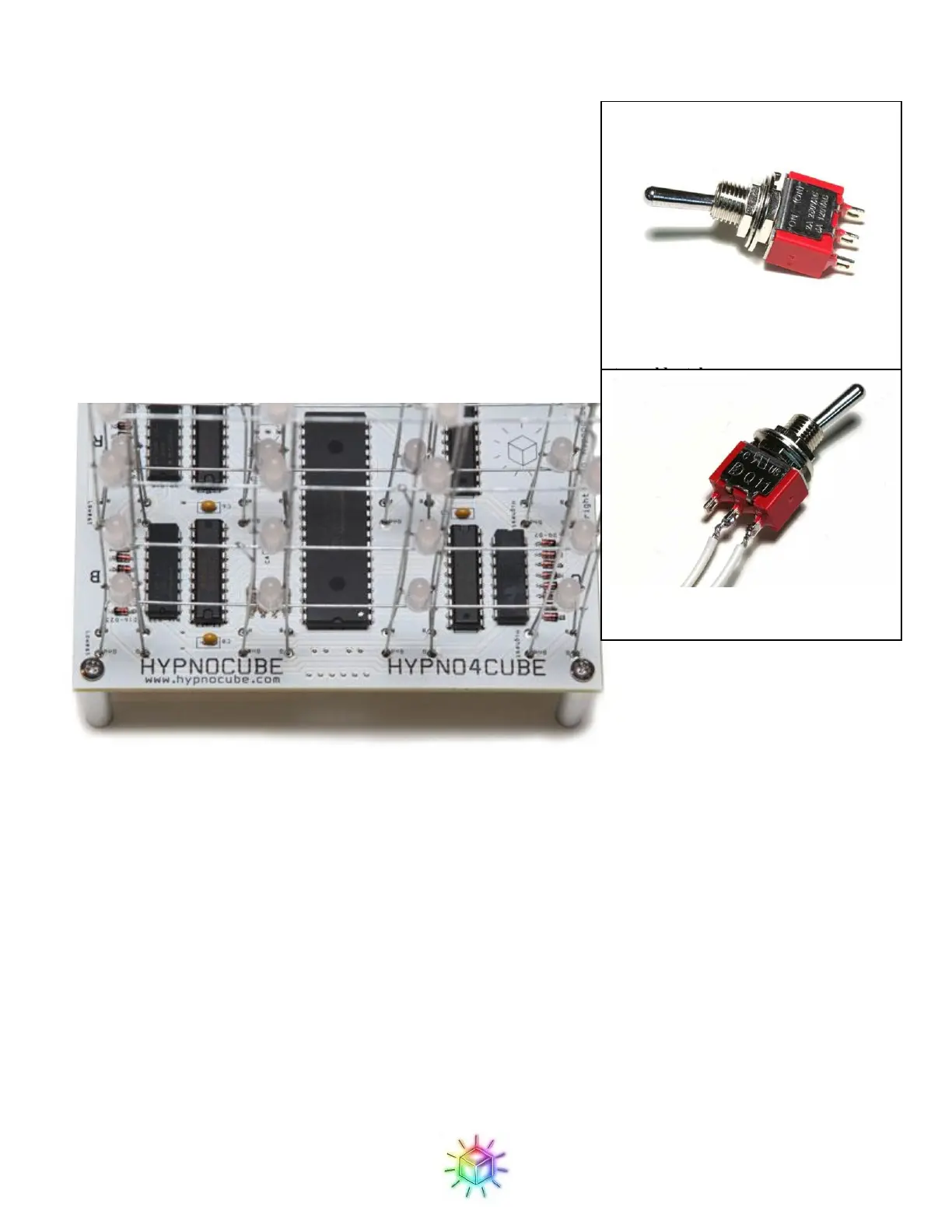
Step 5: Attaching the buttons
Well, we’re calling them buttons to differentiate from the power
switch, but they are actually momentary toggle switches. Because
these switches have a defined rest position, it is important to wire them
properly (otherwise they will be “pressed” except when you’re
actually pressing them!) Solder the white wires to the middle tab, and
the tab on the same side as the lever in its rest position.
We will then attach the buttons to the two button pads on the front side
of the PCB. Figure 73 shows a close up of the area (the button pads
are marked on the underside.) Since the buttons are just making a
connection, polarity does not matter.
Figure 73: Button footprints on PCB.
Step 6: Mounting in the case
Alright, one last step! At this point you should have a fully functioning cube, so it’s just a matter of mounting it
in the case for presentation and protection.
First, remove the nuts and washers from the switches and power jack if you have not already done so. Next
place the cube on its side (with the LED planes aligned vertically) as shown in the Figure 74. The USB jack
should be toward the side of the case with the large hole. Now place the power switch through the nearest hole
on the front of the case (the leftmost hole as viewed from the front of the case) and secure in place with its nut.
We like to place the power switch oriented so that it is up in the off position and down when on, but you can do
differently if you prefer.
Figure 71: Momentary toggle switch – in
this picture, you would use the bottom
two solder tabs
Figure 72: Wired momentary toggle
switch
 Loading...