1400 SRM 1426 DriveAxleRepair
6. Disconnect brake line connecting master cylinder
to brake manifold located on top of drive axle as-
sembly. See Figure 4.
7. Remove parking brake cable. Refer to section
Brake System 1800 SRM 1135 for procedures.
8. Place blocks under drive axle assembly and con-
nect slings and lifting device to drive axle.
9. Place blocks under transmission to support the
transmission while removing drive axle.
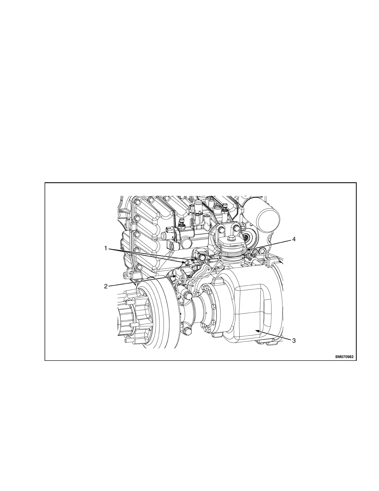
10. Remove two bolts and remove universal joint
from transmission. See Figure 3.
11. Remove transmission isolator mounting bolt
from transmission mounting bracket, located on
topofdriveaxleassembly.SeeFigure7.
12. Remove four drive axle mounting capscrews from
hanger assembly. See Figure 4.
13. Remove blocks, lower drive axle assembly, and
disengagethedriveaxleassemblyfromtrans-
mission.
14. Place blocks under the drive axle center section
assembly.
15. Remove the drive axle shafts, hub/brake drum
assemblies, and back plates. Refer to the section
Brake System 1800 SRM 1135.
16. Remove hanger assembly capscrews and hanger
assembly. Repeat this step on the opposite side.
SeeFigure4.
1. BOLTS
2. UNIVERSAL JOINT
3. DRIVE
AXLE CENTER SECTION
4. TRANSMISSION MOUNTING BRACKET
Figure 3. Universal Joint Removal
3