EasyManua.ls Logo

Hyster A214 - User Manual

Hyster A214
25 pages
Print Icon
To Next Page IconTo Next Page
Loading...
Mast Table of Contents
TABLE OF CONTENTS
General ............................................................................................................................................................... 1
Description ......................................................................................................................................................... 1
Operation............................................................................................................................................................ 1
Control Valve, Carriage/Attachment ............................................................................................................ 2
Selector Valve................................................................................................................................................. 2
Safety Procedures When Working Near Mast.................................................................................................. 3
Carriage Repair.................................................................................................................................................. 5
Remove ........................................................................................................................................................... 5
Disassemble ................................................................................................................................................... 5
Assemble ........................................................................................................................................................ 7
Install ............................................................................................................................................................. 7
Selector Valve................................................................................................................................................. 8
Remove and Disassemble.......................................................................................................................... 8
Clean and Inspect...................................................................................................................................... 8
Assemble.................................................................................................................................................... 8
Install......................................................................................................................................................... 8
Tilt Cylinders Repair ......................................................................................................................................... 9
Remove ........................................................................................................................................................... 9
Disassemble ................................................................................................................................................... 9
Clean .............................................................................................................................................................. 10
Assemble ........................................................................................................................................................ 10
Install ............................................................................................................................................................. 11
Mast Repair........................................................................................................................................................ 11
Remove ........................................................................................................................................................... 11
Disassemble ................................................................................................................................................... 14
Clean and Inspect .......................................................................................................................................... 14
Assemble ........................................................................................................................................................ 16
Install ............................................................................................................................................................. 17
Lift Cylinders Repair ......................................................................................................................................... 19
Description and Operation............................................................................................................................ 19
Remove ........................................................................................................................................................... 20
Disassemble ................................................................................................................................................... 20
Clean and Inspect .......................................................................................................................................... 20
Assemble ........................................................................................................................................................ 20
Install ............................................................................................................................................................. 22
Mast Operation Check....................................................................................................................................... 23
Lift and Tilt System Leaks Check..................................................................................................................... 23
Lift System..................................................................................................................................................... 23
Tilt System..................................................................................................................................................... 23
Tilt Cylinder Stroke and Backward Tilt Angle Adjustments .......................................................................... 25
Carriage Adjustments........................................................................................................................................ 26
Lift Chain Adjustments................................................................................................................................. 26
Bearing Blocks............................................................................................................................................... 26
Mast Adjustments.............................................................................................................................................. 26
Bearing Blocks............................................................................................................................................... 26
Wear Plates .................................................................................................................................................... 26
Troubleshooting.................................................................................................................................................. 28
©2006 HYSTER COMPANY i
Question and Answer IconNeed help?

Do you have a question about the Hyster A214 and is the answer not in the manual?

Overview

The device manual describes the operation, maintenance, and repair procedures for the masts used on a series of lift trucks. This includes information on the lift cylinders, lowering control valves, carriage, and tilt cylinders.

Function Description

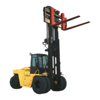
The mast is a critical component of the lift truck, responsible for lifting, lowering, and tilting loads. It consists of vertical frames called weldments, specifically an outer weldment and an inner weldment. Load rollers and bearing blocks are installed on both weldments, guiding their movement as the mast lifts and lowers. The mast can tilt forward and backward, controlled by tilt cylinders installed between the lift truck frame and the outer weldment. Pivot mounts at the bottom of the outer weldment connect the mast to the lift truck, allowing it to rotate on pivot pins during tilting.

The mast also features a carriage, a separate section that moves within the vertical channels of the inner weldment on load rollers. The forks and fork positioner cylinders are attached to the carriage. Two single-stage lift cylinders are installed at the back of the mast. The base of each lift cylinder is held to a mount plate at the bottom of the outer weldment, with hydraulic fittings and external lowering control valves passing through a hole in the mount plate. The cylinder rod of each lift cylinder is positioned at the top of the inner weldment.

Two lift chains control the carriage's movement. These chains are fastened to mounts near the top of the outer weldment, pass over chain sheaves on the inner weldment, and then connect to the carriage. When lift cylinders raise a load on the carriage, the weight of the load and carriage assembly is transferred from the carriage through the chains to the outer weldment. When the lift cylinders retract, the weight of the load, carriage, and inner weldment push oil from the lift cylinders. This oil flows through lowering control valves, the main control valve, and then to the hydraulic tank.

Hydraulic functions for the carriage and attachments are controlled by an auxiliary control valve. The operator actuates this valve with switches in the operator's compartment. Oil from the auxiliary control valve moves the auxiliary spool in the main control valve, which then directs oil to selector valves for carriage functions like fork positioners. When a switch is pushed, a solenoid on the auxiliary control valve and a solenoid on the selector valve are energized. The auxiliary control valve solenoid opens, allowing oil to flow through a pilot line to move the auxiliary spool. The opposite end of the auxiliary spool drains through another solenoid on the auxiliary control valve. As the auxiliary spool moves, it directs hydraulic pump oil to the selector valve.

A selector valve opens and closes a hydraulic circuit for a specific function. Each valve has one solenoid operating one spool. Selector valves are mounted on a common hydraulic manifold on the carriage. The carriage and attachment control valve starts and stops oil flow to the manifold, and the selector valve directs oil to the relevant cylinder(s). The operator controls selector valves with separate switches for each hydraulic function, simultaneously operating the control valve and a selector valve.

The lift cylinders are piston-type, single-action cylinders. Hydraulic oil entering the base extends the rod, while oil draining from the cylinder allows the weight of the carriage and inner weldment to retract the rods. During lifting, oil from the main control valve flows to the bottom of the lift cylinders, and air/leakage on top of the pistons is forced through breather lines back to the hydraulic tank. Lift cylinders have a single-lip seal on the piston to prevent hydraulic oil leaks past the piston and retainer. Small internal leaks are permitted if the hydraulic system's internal leak rate meets specifications.

A lowering control valve is installed in the base of the lift cylinders. This valve allows easy oil entry during lifting but restricts flow during retraction, controlling the maximum lowering speed of a load. The orifice sleeve's position is controlled by oil flow, and the plunger's position by oil pressure and spring tension. During lifting, oil enters the cylinder through the main sleeve's center to large holes, then flows between the plunger and bore to move the orifice sleeve to the plunger's end. The orifice sleeve flange aligns with the large bore part in the body, allowing oil to flow around the orifice sleeve to the cylinder's inlet port. During lowering, oil from the cylinder moves the orifice sleeve away from the larger bore area, creating a restriction. As pressure increases, the plunger moves against a spring, closing the large holes in the main sleeve. All oil must then pass through small holes to the main sleeve's center, limiting cylinder rod lowering to a controlled speed.

Usage Features

The manual emphasizes safety procedures when working near the mast. It instructs operators to always lower the mast and carriage completely, push the lift/lower control lever forward to ensure no movement, and confirm all moving parts are fully lowered. If parts must be raised, a safety chain must be installed to restrain them, connecting moving parts to a non-moving part. The mast should be put in a vertical position, then raised to align the inner weldment's bottom below the tilt cylinder anchor. A 1/2-inch minimum safety chain with a hook should fasten the weldments, ensuring the inner weldment cannot lower. The chain should be installed on both sides, with hooks fully engaged. The mast should then be lowered until the safety chain is taut. If the engine is running, it must be stopped, and the parking brake applied. "DO NOT REMOVE" tags should be placed on the safety chain and a "DO NOT OPERATE" tag in the operator's compartment.

The manual also warns against putting any part of the body into or under the mast or carriage unless all parts are completely lowered or a safety chain is installed, power is off, and the key is removed. Forks can cause injury when the mast is raised. Climbing on the mast or lift truck is prohibited; a ladder or personnel lift must be used. Blocks should not be used to support or restrain mast weldments. Mast repairs often require disassembly and removal of parts, necessitating adherence to specific repair procedures.

For carriage repair, a lifting device is required due to the heavy components. When disconnecting lift chains from the carriage, they must be temporarily connected with wire to a crossmember on the inner weldment to prevent them from falling. A weight (approximately 454 kg or 1000 lb) should be placed on the forks for stability when the carriage is disconnected from the mast. The inner weldment can be raised using lift cylinders or a lifting device. The carriage itself can weigh up to 2270 kg (5000 lb), and forks up to 680 kg (1500 lb) each.

Maintenance Features

The manual provides detailed instructions for disassembling, cleaning, inspecting, and assembling various components.

Carriage Repair Maintenance:

  • Disassembly: Remove fork positioner cylinders, fork pins, forks, and fork guides/carriers. Place the carriage on blocks to keep load rollers off the ground. Remove load rollers and bearing blocks as needed, and selector valves if necessary. Fork positioner cylinders are disassembled by removing retainers, pulling rod assemblies, removing nuts and pistons, and then seals and O-rings.
  • Cleaning: Use solvent to clean metal parts, drying with compressed air. Inspect parts for damage and replace as needed.
  • Assembly: Lubricate seals and O-rings with clean hydraulic oil before installing them in the fork positioner cylinder retainer. Install the rod seal, guide ring, and wiper in the retainer bore. Install the O-ring and piston on the rod, using Loctite® 277 on threads and tightening the nut to 990 to 1090 Nm (732 to 805 lbf ft). Install the piston seal and wear ring, then the rod and piston in the shell, and finally the retainer.
  • Load Rollers: Lubricate bearings with multipurpose grease. Install load rollers on shafts, then retainers and capscrews (tighten to 26 N•m or 19 lbf ft). Measure clearance between retainer and outer bearing, adding shims for zero clearance. Retighten capscrews to 53 N•m (39 lbf ft) and ensure free rotation.
  • Bearing Blocks: Install mounts and tighten capscrews to 53 N•m (39 lbf ft). Install bearing blocks and shims, lubricating surfaces with multipurpose grease.
  • Installation: Use the hydraulic system or a lifting device to raise the inner weldment above the carriage, then carefully lower it to engage all load rollers. Check bearing block clearance. Connect lift chains to chain anchors with new cotter pins. Install fork positioner cylinders, fork guides/carriers, forks, and fork pins with retainers. Connect electrical connectors and hydraulic lines. Check lift chains as described in "Lift Chain Adjustments."

Selector Valve Maintenance:

  • Removal/Disassembly: Disconnect electrical wires and hydraulic lines. Remove capscrews holding selector valves to the carriage. Remove the nut and solenoid coil from the housing, then the spool and O-rings.
  • Cleaning/Inspection: Use solvent to clean metal parts, drying with compressed air. Inspect parts for damage and replace as needed.
  • Assembly: Lubricate cartridges with clean hydraulic oil. Install O-rings on cartridges, then cartridges into valve bodies. Install solenoid coils and nuts. Install O-rings and plugs in valve bodies. Install selector valves together with new O-rings, tightening through bolts.
  • Installation: Mount selector valve assembly on the carriage, installing capscrews and washers. Connect hydraulic lines and wires to solenoids.

Tilt Cylinders Repair Maintenance:

  • Removal: Tilt mast forward and use a chain to hold it to the frame. Disconnect hydraulic lines, capping them. Remove pivot pin retainers and push pivot pins out of the rod end with a tool. Use a lifting device to move tilt cylinders, removing retainers and pivot pins from frame mounts.
  • Disassembly: Remove rod end from rod. Remove retainer from shell, then rod and piston assembly. Disassemble cylinder as needed.
  • Cleaning: Clean all parts in solvent and dry with compressed air.
  • Assembly: Always use new seals and O-rings, ensuring all parts are clean and lubricated with clean hydraulic oil. Install O-ring inside piston bore, then piston on rod (ensure O-ring is not damaged). Tighten nut to 1500 to 1600 N•m (1100 to 1180 lbf ft). Install O-ring, seal ring, and wear ring on piston (heat seal ring before installation, push into groove with ring compressor, let cool). Install wiper, backup ring, single-lip seal, and wear ring in retainer. Install O-ring on retainer's outside. Carefully install retainer on rod, engaging threads and tightening to 550 to 625 N•m (400 to 450 lbf ft) with a spanner. Install lowering control valve, ensuring special washer and spring are correctly installed.
  • Installation: Install rod end on rod. Use a lifting device to position tilt cylinders on the lift truck. Lubricate pivot pin and install in frame (grease fitting outward). Install retainer pin. Install pivot pin at mast mount and retainer pin, tightening capscrews. Install relief valves at rod end ports and connect hydraulic lines. Operate tilt cylinders, check for leaks, and adjust as needed.

Mast Repair Maintenance:

  • Removal: Lower lift mechanism completely. If mast must be disassembled, remove forks and carriage (or fasten carriage to a crossmember). Connect a lifting device to lifting eyes at the top of the outer weldment, ensuring capacity. Raise lifting device for mast stability. Clean hydraulic fitting area, disconnect hydraulic lines, and cap them. Disconnect header hoses and electrical cable. If carriage and forks are installed, remove them. Put mast in vertical position, remove capscrews from mast mounting pins. Raise mast slightly, place blocks under tilt cylinders, remove anchor pins. Remove mast from lift truck, positioning it with crossmembers facing up.
  • Disassembly: Remove lift chain pins at chain anchors. Remove capscrew and washers from top of each lift cylinder, then retainers. Remove capscrew and washers from bottom mount. Slide inner weldment from outer weldment (approx. 15 cm or 6 in.) to disengage lift cylinders. Use a lifting sling to remove lift cylinders from mount plates. Remove bearing block assemblies and wear plates from outer weldment. Slide inner weldment halfway out, then completely out, using a lifting device. Remove load rollers and bearing blocks as needed. Remove and disassemble chain sheaves.
  • Cleaning/Inspection: Inspect sheaves and load rollers for wear/damage (do not use steam). Lubricate bearings with multipurpose grease. Inspect lift chains for wear/damage; replace if 3% longer than new. Lubricate chains with SAE 30 engine oil (soaking is recommended). Inspect chain anchors and pins for wear/damage. Clean mast with steam or solvent. Inspect sliding/rolling surfaces and welds for damage/cracks.
  • Assembly: Do not weld on any mast assembly part without consulting a Hyster dealer. Shims for bearing blocks and wear plates ensure correct clearance.
    • Load Rollers: Lubricate bearings with multipurpose grease. Install load rollers on shafts, then retainers and capscrews (26 N•m or 19 lbf ft). Measure clearance, add shims for zero clearance, retighten capscrews to 53 N•m (39 lbf ft), ensure free rotation.
    • Bearing Blocks: Install mounts and tighten capscrews to 53 N•m (39 lbf ft). Install bearing blocks and shims on inner/outer weldments, lubricating surfaces with multipurpose grease.
    • Inner Weldment: Connect a lifting device to the inner weldment center. Put load rollers into outer weldment end. Slide inner weldment into outer weldment until aligned.
    • Bearing Block Assemblies: Install at top of outer weldment.
    • Wear Plates: Lubricate back of inner weldment with multipurpose grease. Install wear plates and shims at back of outer weldment.
    • Adjustments: Adjust bearing blocks and wear plates as described in "Mast Adjustments."
    • Lift Cylinders: Use a lifting device to install lift cylinders. Install washers and capscrews at bottom. Push inner weldment to engage rods. Install capscrews and washers to hold top of cylinder rods. Install retainers for cylinders at top of outer weldment.
    • Lowering Control Valves: Ensure installed at bottom of both lift cylinders.
    • Chain Sheaves: Lubricate bearings with multipurpose grease. Install bearings in chain sheave. Install chain sheave and inner spacer in bracket, then shaft. Install spacer and retainer (26 N•m or 19 lbf ft). Measure clearance, add shims for zero clearance, retighten capscrews to 53 N•m (39 lbf ft), ensure free rotation.
    • Lift Chains: Connect to outer weldment. Attach wires between chain ends and inner weldment crossmember to control chains during mast installation.
  • Installation: Ensure bushings and snap rings for tilt cylinder pins are installed in frame and outer weldment. Install tilt cylinders to frame mounts (grease fittings outward). Install pivot pins and anchor pins. Connect a lifting device to mast assembly top, ensuring inner/outer weldments are fastened and chains don't damage hydraulic lines. Raise mast to vertical position and move onto lift truck. Lubricate mast mounting pins and bushings with multipurpose grease. Install mast mounting pins through frame and into mast. Install caps, nuts, and bolts (grease fitting on cap toward front), tighten bolt to 176 N•m (130 lbf ft). Connect tilt cylinders to outer weldment (grease fittings outward). Install carriage and forks. Connect hydraulic lines to mast assembly. Install connection hoses, header hoses, and electrical cable (assemble hose sheaves if disassembled). Adjust lift chains, carriage, and tilt cylinders.

Mast Operation Check:

  • Check for hydraulic system leaks, hose, and tube condition.
  • Raise/lower mast several times without load, ensuring smooth movement and correct sequence.
  • Confirm inner weldment and carriage lower completely.
  • Check attachment controls for correct function and no leaks.

Lift and Tilt System Leaks Check:

  • Lift System: Raise/lower mast several times with and without capacity load. Check for leaks. If carriage lowers slowly in Neutral, internal hydraulic system leaks exist. Check lift cylinder internal leaks by removing load, installing gate valves in supply lines, then reapplying load and raising carriage 1m (3 ft). Close both gate valves; if carriage/inner weldment lowers, lift cylinder seals leak. If carriage doesn't move, open gate valves one by one to check movement and hydraulic line/fitting leaks. If no leaks, main control valve may be damaged.
  • Tilt System: Apply capacity load, raise forks 30 cm (12 in.). Slowly tilt mast forward. If mast continues to tilt slowly in Neutral, internal hydraulic system leaks exist. If leak rate exceeds specification, remove load, install gate valve between front port of each tilt cylinder and hydraulic line. Reapply load. Close one valve; if mast tilts slowly, the cylinder connected to the closed valve has leaking seals. Check other cylinder similarly. If mast doesn't move, open one gate valve to check movement and hydraulic line/fitting leaks. If no leaks, main control valve may be damaged.

Hyster A214 Specifications

General IconGeneral
BrandHyster
ModelA214
CategoryForklifts
LanguageEnglish

Related product manuals