3
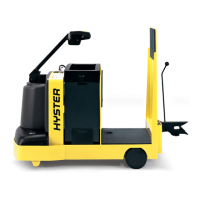
The magnetic polarity of a coil may be determined by
the “Right Hand Rule for COILS” if the direction of
current flow is known. To apply this rule, imagine
grasping the coil with the right hand so the fingers are
pointed in the direction of current flow; then the thumb
will point toward the north pole of the coil.
6922
FIGURE 3. ELECTROMAGNETS
Some electromagnets have an iron core or armature
which moves when the coil of wire is energized. The
movable component has a south pole generated adjacent
to the north pole of the coil because of the magnetic lines
from the coil. Since iron is a better conductor of
magnetic lines than air, the lines enter the movable
component and return through air to the pole at the
opposite end of the coil. The magnetic attraction pulls
the movable component towards the coil when current
flows. This type of electromagnet is often called a
“Solenoid.”
ELECTROMAGNETIC INDUCTION
The principle of electromagnetic induction is to produce
a voltage by a change in the magnetic field. Any change
(increase or decrease) in the current flow in the primary
will create (induce) a voltage in the secondary. A change
in voltage in a closed circuit is also accompanied by a
corresponding change in current. The most common
application of this principle is the transformer. Two
stationary windings are placed over a common
laminated steel coil. The primary winding is excited by
a fluctuating current source. A change in magnetism by
the primary winding will induce a voltage in the
secondary because both windings are linked together
magnetically. The ignition coil and SCR pulse
transformer operate on this principle.
EXPANDING MAGNETIC FIELD
(GENERATED BY CURRENT FLOW
THROUGH PRIMARY WINDINGS
INDUCES
VOLTAGE IN
SECONDARY
WINDINGS
LAMINATED
IRON CORE
6923
PRIMARY
SECONDARY
FIGURE 4. ELECTROMAGNETIC INDUCTION
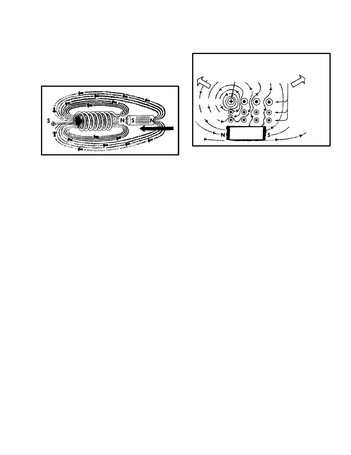
MAGNETIC FORCE ON A CONDUCTOR
When a current–carrying conductor is positioned in a
magnetic field there is a distortion of the normal lines of
force between the poles. Magnetic lines of force in the
same direction join together to make a stronger field.
Lines of force in the opposite direction tend to cancel
out which creates a weaker field. Under these conditions
the conductor moves toward the weaker field.
The upper LH quarter of FIGURE 5. shows the current
flowing into the left–hand side and out of the right–hand
side. There will be a tendency for the conductor to turn
in a clockwise direction. Current flow through the
left–hand conductor creates a clockwise field around the
conductor. The lines of force below the conductor join
with the lines of force from the permanent magnet and a
strong field is produced. The lines of force above the
conductor oppose the lines of force from the permanent
magnet and a weak field is produced. The result is an
upward movement of the left–hand conductor. Since the
current flow through the right–hand conductor is in the
opposite direction, a counterclockwise field is created
around the conductor. This causes the right–hand
conductor to move downward. The commutator will
change the direction of current when the conductors
travel past the neutral point.
 Loading...