RELAYS
Except for the main relays shown on Figure 3, all
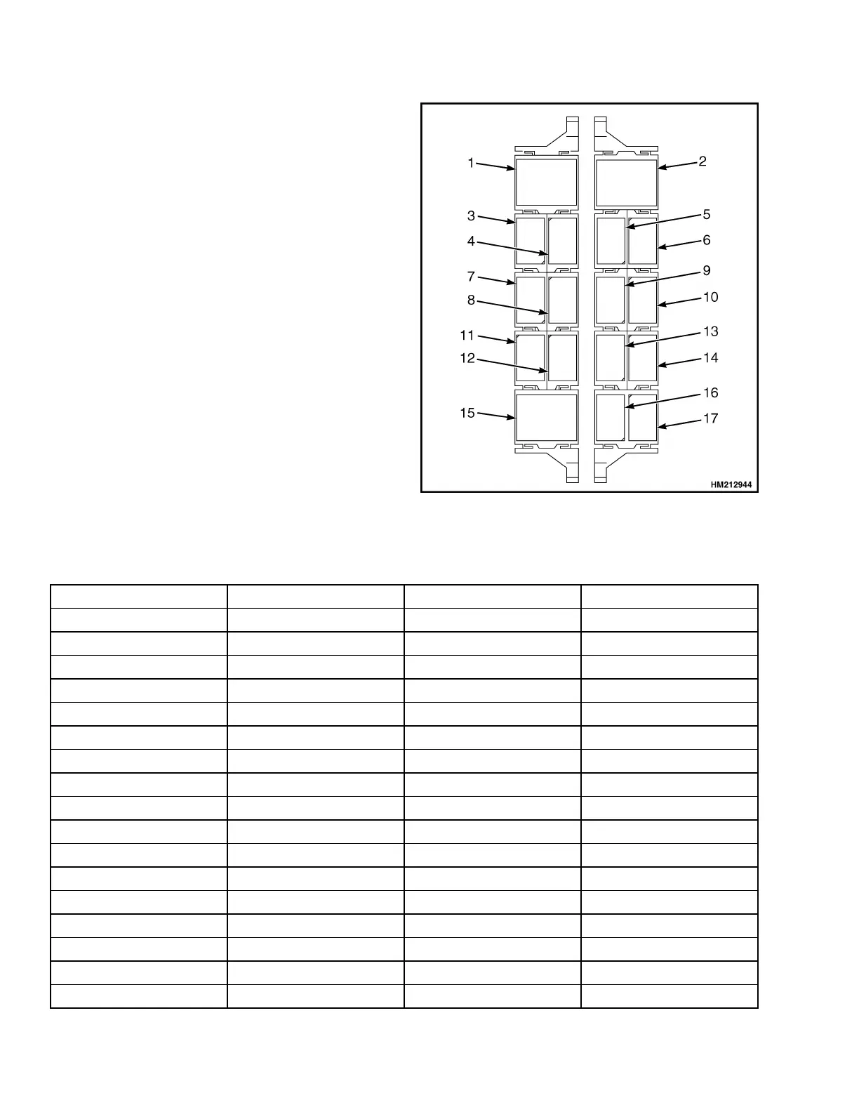
relays are installed on the relay panel that is loca-
ted left of the fuse panel. See Figure 5 and Table 7.
Figure 5. Relay Panel
Table 7. Relays Overview
Item Description Connector Location
1 Main Power CPS16 [26,E]
2 Lights CPS174 [96,B]
3 Horn CPS84 [166,C]
4 OPS CPS84 [134,I]
5 Start Enable CPS15 [26,F]
6 Ignition CPS15 [30,C]
7 Hydraulic Controller CPS120 [138,F]
8 Twistlock CPS120 [145,E]
9 Start Inhibit CPS13 [29,B]
10 Neutral CPS13 [29,B]
11 12 Volt Relay CPS108 [165,F]
12 Override CPS108 [106,C]
13 AC3 CPS36 [178,F]
14 Reverse Lights & Alarm CPS36 [81,I]
15 Flasher Unit CPS76 [91,B]
16 AC1 CPS115 [178,F]
17 AC2 CPS115 [178,F]
Electrical Schematic and System Description 2200 SRM 1944
16