Do you have a question about the HYT TC-700 and is the answer not in the manual?
Manual intended for experienced technicians familiar with similar equipment.
General safety precautions for operation, service, and repair of the equipment.
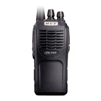
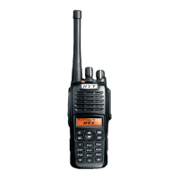
Identifies and describes the radio's keys, controls, and indicators.
Details conventional and squelch mode features, channel spacing, and signaling.
Explains User Mode, All Reset Mode, and cloning procedures.
Details how to enter and operate the manual adjustment mode.
Describes procedure for cloning via wireless transmission.
Describes procedure for cloning via wired connection.
Describes frequency setting parameters for manual adjustment.
Lists adjustment items for the first group.
Lists adjustment items for the second group.
Describes PC adjustment mode using programming software.
Explains the radio's power supply system, including voltage regulation.
Describes the Phase-Locked Loop circuit for signal generation.
Details PLL step frequency and phase comparison mechanism.
Explains Voltage Controlled Oscillator function in transmit/receive modes.
Describes the unlock detection mechanism and its function.
Overview of the receiver's double conversion superheterodyne architecture.
Describes the initial RF signal amplification stage.
Explains the first mixer's function in IF signal generation.
Details the IF amplifier stages and signal processing.
Explains the circuit for switching between narrow and wide bands.
Describes the audio frequency amplifier stage driving the speaker.
Explains AF signal processing and signaling generation for transmission.
Details the RF power amplifier stages for output power.
Describes antenna switching and low-pass filter functions.
Explains the Automatic Power Control circuit's function.
Explains CTCSS/CDCSS signaling in transmit and receive modes.
Describes 5-Tone and DTMF signaling processing.
Explains MSK signaling transmission and reception.
Details AF signal processing for transmit and receive audio.
Shows the block diagram of the MCU control system.
Explains the functions of the MCU control circuit.
Detailed list and description of each CPU pin function.
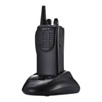
Overview of the TC-700 desktop charger and its adopted IC.
Details the functions of the bq2000T charging IC for battery management.
Shows the pinout and configuration of the bq2000T IC.
Explains the function of each pin on the bq2000T IC.
Discusses methods for terminating battery charging based on various criteria.
Explains how maximum charge time is set via the RC pin.
Describes temperature-based charge termination using the TS pin.
Explains peak voltage detection for Ni-Cd/Ni-MH charge termination.
Details how the charger controls charging current via the MOD pin.
Lists necessary equipment for radio adjustment procedures.
Explains how to perform reset and initial adjustments in user mode.
Details adjustment methods for transmitter parameters like power and deviation.
Procedure for adjusting the low TX power output.
Procedure for adjusting the CDCSS balance parameter.
Procedure for adjusting CDCSS deviation for different bandwidths.
Procedure for adjusting high CTCSS deviation for different bandwidths.
Procedure for adjusting AK2346 transmit audio deviation.
Procedure for adjusting 5-tone deviation.
Procedure for adjusting DTMF deviation.
Procedure for adjusting MSK deviation.
Adjustment procedure for VOX gain setting 1.
Adjustment procedure for VOX gain setting 5.
Procedure for adjusting the high TX power output.
Procedure for adjusting the low TX voltage.
Details receiver adjustment procedures.
Procedure for adjusting receiver sensitivity.
Procedure for adjusting AK2346 RX volume.
Procedure for adjusting Squelch Level 3 (OPEN).
Procedure for adjusting Squelch Level 3 (SQUELCH).
Procedure for adjusting Squelch Level 9 (OPEN).
Procedure for adjusting Squelch Level 9 (SQUELCH).
Procedure for adjusting low RX voltage.
Flowchart for troubleshooting MCU related hardware and software issues.
Flowchart for troubleshooting issues related to the Voltage Controlled Oscillator circuit.
Flowchart for troubleshooting transmitter circuit failures.
Flowchart for troubleshooting receiver circuit issues.
Steps to remove the radio's case assembly.
Steps to remove the speaker and its gasket.
Steps to remove the Tx-Rx unit from the radio chassis.
Important notes for reassembling the radio, especially regarding seals and wiring.
Steps for attaching the case assembly to the chassis, ensuring proper fit.
Summary of general radio specifications including frequency, channels, and voltage.
Summary of receiver performance specifications like sensitivity and noise levels.
Summary of transmitter performance specifications like RF power and modulation.
| Channel Capacity | 16 |
|---|---|
| RF Power Output | 5W |
| Channel Spacing | 12.5 / 25 kHz |
| Frequency Stability | ±2.5 ppm |
| Antenna Impedance | 50Ω |
| Modulation | 16KΦF3E / 11KΦF3E |
| Spurious Emission | ≤ -36 dBm |
| Audio Distortion | ≤5% |
| Receiver Sensitivity | ≤0.25μV (12dB SINAD) |
| Intermodulation | ≥60dB |
| IP Rating | IP54 |
| Frequency Range | 400-470MHz |
| Operating Temperature | -30 °C to +55 °C |
| Adjacent Channel Power | ≥60dB |
| Selectivity | 70dB |
| Spurious Response Rejection | 70 dB |
| Audio Power Output | 1W |
| Dimensions | 125x55x35mm |