Home
Hytera
Accessories
DS-6210U5C4
Hytera DS-6210U5C4 User Manual
4
of 1
of 1 rating
61 pages
Give review
Manual
Specs
To Next Page
To Next Page
To Previous Page
To Previous Page
Loading...
Owner's Man
ual
Product Contr
ols
17
2.4.2
Fr
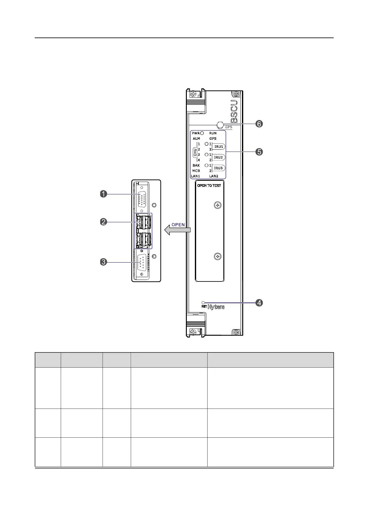
ont Panel
The front pan
el of the BS
CU is illustrat
ed below
.
Figure
2-9
Fr
ont Pa
nel of BSC
U
No.
Name
Qt
y.
Descrip
tion
Descrip
tion
1
Video
graphics
array
1
For debugg
ing
DB1
5
-
connector
(female)
2
USB
Interfac
e
4
For debugg
ing
A-
connector (f
emale)
3
RS232
Interfac
e
1
For debugg
ing
DB9
-
connector (ma
le)
18
20
Table of Contents
Default Chapter
3
Table of Contents
3
1 Checking Items in the Package
10
Figure 1-1 Packing List
10
2 Product Controls
11
Interface Units of 4-Carrier Base Station
11
Figure 2-1 Interface Units of 4-Carrier Base Station
11
Antenna Connector
12
Eib
12
Figure 2-2 Antenna Connector of 4-Carrier Base Station
12
Table 2-1 Descriptions on Interface Units of 4-Carrier Base Station
12
Table 2-2 Descriptions on Antenna Connector of 4-Carrier Base Station
12
Figure 2-3 EIB of 4-Carrier Base Station
13
Table 2-3 Descriptions on EIB of 4-Carrier Base Station
13
Figure 2-4 Power Supply Interface of 4-Carrier Base Station
14
Power Supply Interface
14
Table 2-4 Descriptions on Power Supply Interface of 4-Carrier Base Station
14
Cartridge
15
Channel Unit (CHU)
15
Function
15
Figure 2-5 Full Configuration for MC
15
Figure 2-6 Logical Architecture of CHU
15
Front Panel
16
Figure 2-7 Front Panel of CHU
16
LED Indicator
17
Table 2-5 Description on Front Panel of CHU
17
Base Station Controller Unit (BSCU)
18
Function
18
Figure 2-8 Logic Architecture of BSCU
18
Table 2-6 Descriptions on CHU Indicators
18
Front Panel
19
Figure 2-9 Front Panel of BSCU
19
LED Indicator
20
Table 2-7 Descriptions on Front Panel of BSCU
20
Power Supply Unit (PSU)
21
Function
21
Table 2-8 Descriptions on BSCU Indicators
21
Front Panel
22
Table 2-9 Descriptions on PSU
22
LED Indicator
23
Figure 2-10 Front Panel of PSU
23
Table 2-10 Descriptions on Front Panel of PSU
23
Interconnect Backboard (ICB)
24
Front View
24
Table 2-11 Descriptions on PSU Indicators
24
Rear View
25
Figure 2-11 Front View of ICB
25
Table 2-12 Descriptions on Front Interfaces of ICB
25
Figure 2-12 Rear View of ICB
26
Table 2-13 Descriptions on Rear Interfaces of ICB
26
Fan
27
Front Panel
27
LED Indicator
27
Figure 2-13 Front Panel of FAN
27
Table 2-14 DIP Switch Settings for ICB
27
Rear Panel
28
Figure 2-14 Rear Panel of FAN
28
Table 2-15 Descriptions on FAN Indicators
28
Table 2-16 Descriptions on Rear Panel of FAN
28
Divider Unit (DIU)
29
Function
29
Front Panel
29
Figure 2-15 Logical Diagram of DIU
29
Figure 2-16 Front Panel of DIU
29
Table 2-17 DIP Switch Settings for FAN
29
Rear Panel
30
Figure 2-17 Rear Panel of DIU
30
Table 2-18 Descriptions on Front Panel of DIU
30
Table 2-19 Descriptions on Rear Panel of DIU
30
Router
31
Function
31
Front Panel
31
Figure 2-18 Front Panel of Router
31
Table 2-20 DIU Address Settings
31
Table 2-21 Descriptions on Front Panel of Router
31
Rear Panel
32
LED Indicator
32
Figure 2-19 Rear Panel of Router
32
Table 2-22 Descriptions on Rear Panel of Router
32
Ip-E1
33
Front Panel
33
Table 2-23 Descriptions on Router Indicators
33
LED Indicator
34
Figure 2-20 Front Panel of IP-E1
34
Table 2-24 Descriptions on IP-E1 Indicators
34
Rear Panel
35
Combiner (COM)
35
Figure 2-21 Rear Panel of IP-E1
35
Table 2-25 Descriptions on Rear Panel of IP-E1
35
Figure 2-22 Logical Diagram of 4-Port Combiner
36
Figure 2-23 Rear Panel of COM
36
Function
36
Rear Panel
36
Table 2-26 Descriptions on Rear Panel of COM
37
3 Installation
38
Cable Layout
38
Safety Information
38
Figure 3-1 Cable Layout
38
Power Supply
39
Working at Heights
39
Installation Preparation
39
Technical Files
39
Personnel
40
Tools
40
Table 3-1 Technical Files
40
Table 3-2 Tools and Meter
40
Unpacking Inspection
41
Check before Unpacking
41
Unpacking Wooden Case
41
Unpacking Cartons
42
Figure 3-2 Removing the Cover
42
Inspections
43
Installing the Cabinet
43
Determine the Installation Position
43
Figure 3-3 Layout of Holes for a Single Cabinet
43
Installing the Cabinet
44
Figure 3-4 Layout of Holes for Combined Cabinet
44
Figure 3-5 Tightening the Bolt
44
Installing Modules into the Cabinet
45
Module Layout
45
Installation Procedures
45
Figure 3-6 of Module Layout
45
Figure 3-7 Opening the Cabinet Door
46
Figure 3-8 Disassembling the Side Door
46
Figure 3-9 Loosening the Ejector
47
Figure 3-10 Installing the BSCU
47
Figure 3-11 Installing the FAN
48
Figure 3-12 Removing the FAN
48
Figure 3-13 Installing the Divider Unit
48
Installing Cables
49
Equipment Status
49
Cables
49
Figure 3-14 Installing the Combiner Unit
49
Figure 3-15 Cable Diagram
49
Figure 3-16 External Cable Connection
50
Table 3-3 Cables Description
50
Table 3-4 Descriptions on the Interface of External Cable Connection
50
Examination after Installation
51
Equipment Status
51
Examining the Cabinet
51
Examining Cables
51
Table 3-5 Checklist of Cabinet Installation
51
Power on and Examination
52
Environment Examination
52
Table 3-6 Checklist of Cables
52
Table 3-7 Checklist of Power Situation
52
Table 3-8 Checklist of Environment on Site
53
4 Basic Operations
54
Powering on
54
Powering off
54
5 Troubleshooting
55
6 Routine Maintenance
56
Purpose
56
Tasks
56
A Abbreviations
57
4
Based on 1 rating
Ask a question
Give review
Questions and Answers:
Need help?
Do you have a question about the Hytera DS-6210U5C4 and is the answer not in the manual?
Ask a question
Hytera DS-6210U5C4 Specifications
General
Brand
Hytera
Model
DS-6210U5C4
Category
Accessories
Language
English
Related product manuals
Hytera DS-6250 U1
26 pages
 Loading...