Do you have a question about the Hyundai Robex 210NLC-9 and is the answer not in the manual?
Describes manual usage, filing, and symbols.
Provides conversion figures for units.
Explains safety hints and specifications.
Explains structure and function of components.
Explains hydraulic circuit and operation.
Explains electrical circuit and components.
Explains power optimization system.
Explains troubleshooting charts.
Gives judgement standards for parts.
Explains removal, installation, and assembly.
Shows bolt specifications and torque values.
Covers safety procedures and precautions.
Details machine and component specifications.
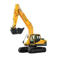
Lists and illustrates the primary parts of the excavator.
Provides detailed technical specifications for the machine.
Details the operational reach and dimensions.
Lists the weight distribution of various assemblies.
Shows load charts for different configurations.
Helps in choosing the appropriate bucket size.
Describes the track system and shoe types.
Provides detailed specs for engine and pumps.
Lists required fluids and lubricants.
Describes the structure and function of the pump.
Details the structure and hydraulic circuit.
Explains the structure and principle of operation.
Describes the structure and driving principle.
Covers structure and functions of the receiver lever.
Explains the structure and function of the pedal.
Details suction, delivery, and return circuits.
Explains pilot circuit operations and systems.
Describes individual hydraulic control operations.
Details combined hydraulic control operations.
Identifies locations of electrical components.
Covers power, starting, and light circuits.
Details specifications for electrical components.
Explains connector destinations and tables.
Provides an overview of the mechatronics system.
Explains power, work, and user mode selections.
Details auto idle pilot lamp functions.
Describes the power boost system.
Explains the travel speed control.
Covers automatic engine warming up.
Details engine overheat prevention.
Explains variable power control.
Describes attachment flow control.
Details the anti-restart function.
Covers error codes and fault diagnosis.
Explains the engine control module.
Details pump and boom priority eppr valves.
Covers cluster and connector information.
Details fuel warmer specifications and operation.
Covers introduction and diagnosing procedure.
Troubleshoots hydraulic and mechanical issues.
Addresses electrical system malfunctions.
Details mechatronics system malfunctions.
Provides standards for performance tests.
Outlines safety and procedural precautions.
Provides torque specifications for components.
Details removal and installation of pump device.
Covers removal, installation, and assembly of control valve.
Details disassembly and assembly of swing device type 1.
Details disassembly and assembly of swing device types 3 and 4.
Covers removal, installation, and assembly of travel device.
Details removal and installation of receiver lever.
Covers removal and assembly of turning joint.
Details disassembly and assembly of cylinders.
Covers removal and installation of undercarriage parts.
Details structure and removal of work equipment.
Provides an introduction to mounting torque.
Details mounting torque for engine components.
Details mounting torque for electrical components.
Details mounting torque for hydraulic components.
Details mounting torque for undercarriage components.
Details mounting torque for structural components.
Details mounting torque for work equipment.
| Brand | Hyundai |
|---|---|
| Model | Robex 210NLC-9 |
| Category | Excavators |
| Language | English |