Do you have a question about the Hyundai Robex 220LC-9SH and is the answer not in the manual?
Safety procedures, protective clothing, emergency preparedness, and hazard avoidance.
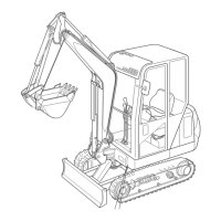
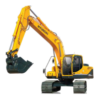
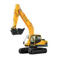
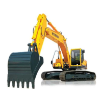
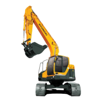
Detailed specifications including operating weight, dimensions, and performance data.
Details the structure and function of the hydraulic pump system.
Explains the structure and hydraulic circuit of the main control valve.
Describes the structure and operating principle of the swing device.
Details the structure and operating principle of the travel device.
Covers the structure and functions of the control lever.
Outlines the structure and function of the control pedal.
Details the hydraulic circuit for cluster type 1.
Explains the suction, delivery, return, and drain circuits of the main system.
Describes the pilot circuit, safety solenoid valve, and priority systems.
Details the operation of individual functions like boom, arm, and bucket.
Explains combined operations of multiple functions for efficiency.
Identifies the locations of electrical components on the machine.
Contains notes on power, starting, and charging circuits for different cluster types.
Lists specifications for various electrical components.
Provides connector destinations and connection tables.
Explains power, work, and user mode selection systems for different cluster types.
Details automatic deceleration systems for cluster types 1 and 2.
Explains travel speed control systems for cluster types 1 and 2.
Covers self-diagnostic systems and error codes for cluster types 1 and 2.
Details the engine control unit (MCU) and ROM exchange method.
Provides an introduction and diagnosing procedure for troubleshooting.
Covers troubleshooting for hydraulic, mechanical, drive, swing, travel, and attachment systems.
Troubleshooting specific electrical issues for cluster type 1.
Troubleshooting specific electrical issues for cluster type 2.
Troubleshooting mechatronics system issues for cluster type 1.
Troubleshooting mechatronics system issues for cluster type 2.
Details the purpose, terminology, and procedures for performance tests.
Maintenance standards for major components like pumps and valves.
Maintenance standards for track and work equipment.
Essential precautions for removal, installation, and assembly work.
Provides torque specifications for major components and a torque chart.
Details removal, installation, and assembly of the pump device.
Covers removal, installation, structure, and assembly of the main control valve.
Details disassembly and assembly for swing devices (types 1, 2, 3).
Explains removal, installation, and disassembly/assembly of the travel device.
Covers removal, installation, and disassembly/assembly of the control lever.
Details removal, installation, and disassembly/assembly of the turning joint.
Explains removal, installation, and disassembly/assembly of cylinders.
Details components and assembly of the undercarriage.
Covers structure and removal/installation of work equipment.
Torque specifications for engine and accessories mounting.
Torque specifications for electrical component mounting.
Torque specifications for hydraulic component mounting.
Torque specifications for undercarriage mounting.
Torque specifications for mounting cab, cowling, and counterweight.
Torque specifications for work equipment mounting.
| Engine Model | Cummins QSB6.7 |
|---|---|
| Fuel Tank Capacity | 400 L |
| Operating Weight | 22, 100 kg |
| Engine Power | 110 kW |
| Engine Power @ RPM | 2, 000 rpm |
| Max Digging Depth | 6, 730 mm |
| Travel Speed | 5.2 km/h |