EasyManua.ls Logo

i-therm AI-7482 - User Manual

i-therm AI-7482
9 pages
Print Icon
To Next Page IconTo Next Page
Loading...
i
(48 X 48)
AI-7482 AI-7782
(72 X 72)
AI-7982
(96 X 96)
AI-7882
(48 X 96)
1. DISPLAY TYPE : Dual 4- Digit 7 Segment LED
4 Digit Bright White (PV)
4 Digit Luminous Green (SV)
STATUS LED’S : OP 1 : Main Control Output
OP 2 : Alarm Status
SOAK : Soak Timer
TUNE : Tuning Status (Only AI-7982)
2. INPUT
Sensor input : TC:J,K,R,S,N,T,B & RTD: Pt-100
Range : Refer below table.
Sampling Time : 125 msec.
Resolution : 1°C/0.C(Only for RTD)
CJC for TC : Built in automatic
LWC for Pt-100 : Built in upto 18E max.
Digital Filter : 1 to 10 Sec.
3. RELAY OUTPUT
Contact type : N/O, CM, N/C
Contact Rating : 5A @ 250VAC or 30 VDC
Life expectancy : > 5,00,000 operations
Isolation : Inherent
4. SSR DRIVE OUTPUT
Drive Capacity : 12V @ 30mA.
Isolation : Non-Isolated.
5. FUNCTION
Output 1 : Main Control output
Output 2 : Programmable
1) Auxiliary control
2) Alarm
3) Soak timer
4) Alarm + Soak timer
Control Action : ON-OFF/PID (Select)
Control Mode : Heat/Cool (Select)
Compliance : ----
6. ENVIRONMENTAL
Operating Range : 0 ~5C, 5~90% Rh
Storage Humidity : 95% Rh (Non-condensing)
7. POWER SUPPLY
Supply Voltage : 90~270VAC, 50/60Hz.
Consumption : 4W Maximum.
8. PHYSICAL
Housing : ABS Plastic
USERS OPERATING MANUAL FOR PID DIGITAL TEMPERATURE CONTROLLER
(Models: AI 7482 / 7882 / 7782 / 7982 / 7682)
SPECIFICATIONS : -
SAFETY INSTRUCTION :
This controller is meant for temperature control
applications. It is important to read the manual prior to
installing or commissioning of controller. All safety
related instruction appearing in this manual must be
followed to ensure safety of the operating personnel as
well as the instrument.
GENERAL
v The controller must be configured correctly for intended
operation. Incorrect configuration could result in
damage to the equipment or the process under control
or it may lead personnel injury.
v The controller is generally part of control panel and in
such a case the terminals should not remain accessible
to the user after installation.
MECHANICAL
v The Controller in its installed state must not come in
close proximity to any corrosive/combustible gases,
caustic vapours, oils, steam or any other process by-
products.
v The Controller in its installed state should not be
exposed to carbon dust, salt air, direct sunlight or
radiant heat.
v Ambient temperature and relative humidity surrounding
the controller must not exceed the maximum specified
limit for proper operation of the controller.
v The controller in its installed state must be protected
against excessive electrostatic or electromagnetic
interferences. Ventilation holes provided on the chassis
of the instrument are meant for thermal dissipation
hence should not be obstructed in the panel.
ELECTRICAL
v The controller must be wired as per wiring diagram & it
must comply with local electrical regulation.
v Care must be taken not to connect AC supplies to low
voltage sensor input.
v Circuit breaker or mains s/w with fuse (275V/1A) must
be installed between power supply and supply terminals
to protect the controller from any possible damage due
to high voltage surges of extended duration.
v Circuit breaker and appropriate fuses must be used for
driving high voltage loads to protect the controller from
any possible damage due to short circuit on loads.
v To minimize pickup of electrical noise, the wiring for low
voltage DC and sensor input must be routed away from
high current power cables. Where it is impractical to do
this, use shielded ground at both ends.
v The controller should not be wired to a 3-Phase supply
with unearthed star connection. Under fault condition
such supply could rise above 264 VAC which will damage
the controller.
v The Electrical noise generated by switching inductive
loads might create momentary Fluctuation in display,
alarm latch up, data loss or permanent damage to the
instrument. To reduce this use snubber circuit across
the load.
v It is essential to install a over Temp. Protection device
to avoid any failure of heating system. Apart from
spoiling the product, this could damage the process
being controlled.
1
OIM AI-7X82 V2.0 Page 1 of 9
Model no.
Display height (PV)
Display height (SV)
AI-7482
0.36 0.56
0.80 0.36
0.36
0.360.360.24
0.39
0.56
AI-7882AI-7782 AI-7982 AI-7682
AI-7682
(96 X 48)
Fe-k(J) T/C
Cr-AL(K) T/C
Sensor Type
Accuracy
o
± 1 C
o
0 ~ 1700 C
o
0 ~ 1700 C
o
0 ~ 1800 C
o
-100 ~ 450 C
Resolution
Range
o
1 C
o
1 C
o
1 C
}
(R) T/C
(S) T/C
TC - N
TC - T
TC - B
Pt-100(RTD)
Pt-100(RTD 0.1)
o
0 ~ 760 C
o
-99 ~ 1300 C
o
-99 ~ 1300 C
o
-99 ~ 400 C
o
-99.9 ~ 450.0 C
o
1 C
o
1 C
o
1 C
o
1 C
o
1 C
o
0.1 C
o
± 0.3 C
Question and Answer IconNeed help?

Do you have a question about the i-therm AI-7482 and is the answer not in the manual?

Summary

Controller Specifications

Display Type

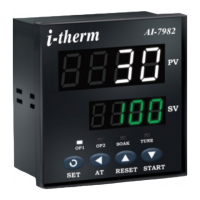
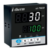
Details the LED display configuration for Process Value (PV) and Set Value (SV).

Status LEDs

Identifies the functions of status LEDs for outputs, soak timer, and tuning.

Input Specifications

Lists supported sensor types (TC, RTD) and their respective ranges and resolutions.

Relay Output

Specifies contact type, rating, life expectancy, and isolation of relay outputs.

SSR Drive Output

Details the drive capacity and isolation for SSR (Solid State Relay) outputs.

Functionality

Outlines main output, programmable auxiliary output, alarm, and soak timer functions.

Environmental Conditions

Specifies operating and storage temperature and humidity ranges.

Power Supply Requirements

Details the required supply voltage range and maximum power consumption.

Physical Housing

Describes the housing material of the controller.

Installation and Panel Layout

Mechanical Installation

Provides instructions for mechanical installation, including panel cut-out dimensions.

Installation Guidelines

Steps for preparing the panel cut-out and securing the controller.

Electrical Installation

Shows electrical connection diagrams for various controller models.

Front Panel Layout Description

Explains the function of each LED, display, and key on the controller's front panel.

Programming and Control Parameters

Programming User List

Details how to access and modify parameters like SP1, SP2, and Soak Time.

Control List Parameters

Explains how to access and set control parameters like Lock Code and PID settings.

Configuration List and Input Settings

Configuration List Access

Instructions to enter configuration mode and set parameters like Lock Code.

Input Type Configuration

Setting the input parameter based on the connected sensor type (TC/RTD).

Advanced Configuration Options

Input Type Settings

Configuring input type based on sensor (TC/RTD) for various models.

Control Mode for Output 1

Selecting the control action algorithm (PID or ON-OFF) for Output 1.

Control Logic for Output 1

Choosing heating or cooling logic for Output 1 based on PV and SP.

Overshoot Control Point

Parameter to manage PV rise rate to minimize overshoot.

Auto Tuning Function

Enabling or disabling the auto-tuning feature for PID control.

Output 2 and Table 3 Settings

Output 2 Configuration

Settings for Set Point 1, Output 2 Mode, Control, Function, and Display.

Table 3: Auxiliary Control Mode

Options for Input Type, Output 2 Logic, and Set Point 2 in Auxiliary mode.

Alarm Mode Configuration

Alarm Type Selection

Defines alarm behavior (Low, High, Deviation, Band) for Output 2.

Alarm Logic

Sets direct or reverse logic for Output 2 activation during alarm conditions.

Alarm Inhibit and Acknowledge

Configuration for alarm inhibit at power on and automatic/manual acknowledgment.

Alarm Set Point

Enables or disables viewing/editing of the Alarm Set Point in the user list.

Soak Timer Configuration

End of Soak Strategy

Defines controller behavior at the end of the soak timer cycle.

Time Base for Soak Timer

Specifies the time unit (minutes, hours) for the soak timer.

Direction of Soak Time

Sets whether the soak timer increments or decrements.

Reset of Running Soak Time

Determines if soak time value is stored during power failure.

Timer Start Mode

Defines the conditions and methods for starting the soak timer.

Auto Tuning and User Guide

Auto Tuning Mode

Instructions to enter and manage the auto-tuning function for PID control.

User Guide: On-Off Action

Explanation of ON-OFF control logic for Heat and Cool modes.

Auto Tuning Process

Details on how the controller learns process characteristics during auto-tuning.

i-therm AI-7482 Specifications

General IconGeneral
MountingPanel mount
Input TypeThermocouple, RTD
Control OutputRelay, SSR
Control AlgorithmPID, On/Off
DisplayLED
Power Supply100-240VAC, 24VDC
CommunicationRS-485 Modbus RTU

Related product manuals