Do you have a question about the i-therm AI-7982 and is the answer not in the manual?
Covers sensor input types, ranges, resolution, and accuracy.
Ensures correct configuration and safe operation for personnel and instrument.
Wiring compliance, protection against surges, and noise reduction.
Selecting the correct sensor input type based on the connected sensor.
Configuring control mode, logic, overshoot, ramp rate, and auto-tune.
Defining alarm types (low, high, deviation, band) and logic.
Instructions on how to enter and enable the auto-tuning function.
Explanation of how auto-tuning works and parameter adjustments.
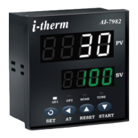
The PID Digital Temperature Controller is a sophisticated device designed for precise temperature management across various industrial and commercial applications. Its primary function is to maintain a desired temperature by continuously monitoring the process value (PV) and adjusting the control output to match the set point (SP). This controller supports a wide range of sensor inputs, including various thermocouple types (J, K, R, S, N, T, B) and RTD Pt-100, ensuring versatility in different thermal environments.
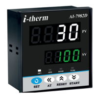
The device features a dual 4-digit 7-segment LED display, with a bright white display for the process value (PV) and a luminous green display for the set point value (SV). This clear visual feedback allows operators to easily monitor the current temperature and the target temperature. Status LEDs provide additional operational insights, indicating the main control output (OP1), alarm status (OP2), soak timer activity (SOAK), and tuning status (TUNE), which is particularly useful for the AI-7982 model during auto-tuning.
One of the key usage features of this controller is its flexible configuration for control actions. Users can select between ON-OFF or PID (Proportional-Integral-Derivative) control algorithms for Output 1, allowing for either simple switching control or more advanced, precise temperature regulation. The PID algorithm is highly effective in minimizing temperature fluctuations and achieving stable control, especially in processes with varying thermal loads. For Output 2, the controller offers multiple programmable functions, including auxiliary control, alarm status, soak timer, or a combination of alarm and soak timer, enhancing its adaptability to complex control strategies.
The controller's programming interface is designed for user-friendliness, allowing operators to easily set parameters such as the control set point (SP1), ramp rate, and various PID constants (proportional band, integral time, derivative time). The ramp rate feature is particularly useful for gradually bringing the process to the set point, preventing overshoot and undershoot, which can be critical in sensitive applications. The device also includes a "tune offset" parameter, enabling auto-tuning to be performed at a specified percentage below the set point, which can be advantageous for optimizing control performance without overshooting the final target.
Alarm management is a critical feature, with Output 2 configurable as an alarm output. The controller supports various alarm types, including low alarm, high alarm, low deviation alarm, high deviation alarm, and band alarm. These alarms can be configured for either direct or reverse acting logic, providing flexibility in how the alarm output responds to process deviations. An alarm inhibit function allows users to prevent alarms from activating at power-on, which can be useful during startup phases. The alarm acknowledgment feature offers options for automatic de-activation, manual acknowledgment via the UP key, or de-activation when the PV falls within programmed limits, ensuring that alarm conditions are managed effectively.
The soak timer function, when configured for Output 2, allows for precise control over temperature holding periods. Users can define the end of soak strategy, determining how the controller behaves once the soak time is complete (e.g., turning off the heater, activating an alarm, or both). The timer base can be set in minutes and seconds, minutes, hours and minutes, or hours, providing granular control over soak durations. The direction for soak time can be configured to increment or decrement, offering flexibility in how the timer operates. A reset of running soak time feature allows users to decide whether the soak time value is stored at power failure or continues from the stored value at power-on, which is important for process continuity.
For maintenance and optimization, the controller incorporates an auto-tuning mode. This feature allows the controller to learn the process characteristics automatically and calculate the optimal PID parameters (P, I, and D values). Auto-tuning can be initiated at any time, but it is recommended to start it when the process is at ambient temperature to minimize overshoot and undershoot during the tuning process. If the initial auto-tuning results are not satisfactory, the manual provides a troubleshooting guide with common symptoms (e.g., slow response, overshoot, oscillations) and corresponding solutions (e.g., decreasing proportional band, increasing integral time), enabling users to fine-tune the PID parameters for optimal control performance.
The controller is also equipped with an adaptive digital filter to smooth out extraneous pulses and noise in the process value signal. This ensures that the control algorithm operates on a stable and accurate PV, leading to more reliable temperature control. The filter time constant can be adjusted to suit the specific noise characteristics of the application.
Safety instructions are paramount, emphasizing the importance of correct configuration to prevent damage to equipment or personnel injury. The manual advises against exposing the controller to corrosive or combustible gases, caustic vapors, oils, steam, carbon dust, salt air, direct sunlight, or radiant heat. Proper ventilation and protection against electrostatic or electromagnetic interferences are also highlighted to ensure reliable operation. Electrical installation guidelines stress the importance of wiring according to the diagram, using circuit breakers and appropriate fuses, and routing low-voltage wiring away from high-current cables to minimize electrical noise. The inclusion of an over-temperature protection device is also recommended to prevent heating system failures and potential damage to the process.
| Brand | i-therm |
|---|---|
| Model | AI-7982 |
| Category | Temperature Controller |
| Language | English |