I/O Signal
Explanation of I/O Signal Functions
Category
Abbreviated
Code
Signal Name Contents of Functions
CSTR Start Signal (PTP Strobe) Starts moving toward the position set in Command Position No.
PC1 to PC256 Command Position No. To input position No. desired to move (binary input)
BKRL
Brake Compulsory
Release
To release the brake compulsorily
RMOD
Operation Mode
Changeover
Operation Mode can be changed over when MODE Switch on the controller
is on AUTO. The setting is AUTO when signal is OFF, and MANU when ON.
*STP Pause
Turn the signal off during operation to decelerate and stop. Turn the signal
ON to resume the operation.
RES Reset
Turn the signal on to reset the alarm. Also, it is possible to cancel the
residual operation if turning on during the pause (*STP is off).
SON Servo ON Turn on to turn the servo ON, and off to turn the servo OFF.
HOME Home return
Perform the home-return operation with the signal rising edge (OFF →
ON).
MODE Teaching Mode
Turn the signal on to set to the Teaching Mode, and off to cancel the
Teaching Mode. The mode will not be switched over unless CSTR, JOG+
and JOG− are all off and the actuator operation is stopped.
JISL Jog/Inching Changeover
Jog Operation can be performed with JOG+ and JOG− while this signal is
off.
Inching Operation is performed with JOG+ and JOG− when it is on.
JOG+
JOG−
Jog
Jog Operation is performed to positive direction by detecting ON edge of
JOG+ signal and to negative direction by JOG− signal while JISL signal is
off. The actuator will decelerate and stop if OFF edge is detected while in
each Jog Operation.
Inching Operation is performed while JISL signal is on.
PWRT Teaching
Write the current position to the indicated position if indicating the written
position and turn this signal on for more than 20ms during the Teaching
Mode.
CLBR
(Specified only
for CA)
Loadcell Calibration
Command
Turn this signal on for more than 20ms to perform calibration of loadcell.
ST0 to ST6 Start Signal 0 to 6
The actuator moves to the commanded position with this signal on during
the electromagnetic valve mode.
(CSTR signal is not required)
TL Torque Limit Select
Puts torque limitation to the motor with the signal on and the value set to
the parameter.
DCRL Deviation Counter Clear Clears the deviation count with the signal on.
Input
CSTP Compulsory Stop
Performs compulsory stop of the actuator. Turn the signal on to decelerate
and stop the actuator and turns the servo off.
PEND/INP Position Completion
Turns on in the positioning band range after actuator operation. PEND
signal will not turn off once it turns on until the next operation even if the
actuator goes off the range of positioning band. INP will turn off. PEND
and INP can be switched over by the parameter.
PM1 to PM256 Completion Position No.
Outputs (binary output) the position No. that is reached at the same time
the positioning is complete.
HEND Home Return Completion
Turns on when home-return operation is complete. It will be kept on unless
the home position is lost.
ZONE1, 2 Zone
Turns on if the current actuator position is within the range set to the
parameter.
PZONE Position Zone
Turns on when the current actuator position gets into the range set to the
position data during the move towards the position. It can be utilized
together with ZONE 1, however, PZONE is effective only when moving
towards the set position.
RMDS Operation Mode Output
Outputs the operation mode status. It turns on when the controller is on
Manual Mode.
*ALM Alarm
Turns on when controller in normal condition, and off when alarm is
generated.
MOVE While in Operation
Turns on during the actuator is moving (including home-return operation
and pressing operation).
SV Servo ON status
Turns on when the servo is on.
*EMGS Emergency Stop Output
Turns on when the controller emergency stop is cancelled, and off during
the emergency stop (regardless of alarms).
MODES Teaching Mode Output
Turns on when it turns to the Teaching Mode by MODE signal input. It is off
in the normal mode.
WEND Writing Complete
Turns on after the writing by PWRT signal is complete in the Teaching
Mode. This signal turns off if PWRT signal is turned off.
PE0 to PE6 Current Position Number
Turns on when moving to the target position is complete in
Electromagnetic Valve Mode.
LS0 to LS2 Limit Switch Output
Turns on when the current actuator position is within the range of
positioning band (±) of the target position. It is output even before the
movement command and the servo is off if the home-return operation is
completed.
CEND
(Specified only
for CA)
Loadcell Calibration
Complete
Turns on after loadcell calibration is complete. This signal turns off if CLBR
signal is turned off.
*BALM
Warning for Absolute
Battery Voltage Drop
Turns on when the battery voltage for the absolute type actuator is within
the normal voltage range. Replace the battery if it is turned off. (this signal
is always on for the incremental type actuator.)
LOAD
Load Output Judgment
Signal
Outputs when current exceeds the value set to “threshold” within range of
position data “ZONE+” or “ZONE−” during the pressing operation.
Utilize this signal for a judgment of a press-fitting process being properly
performed, etc.
TRQS Torque Level Output
Outputs when current of motor reaches the value set to “threshold” by the
slider (or rod) being hit to an obstacle during the pressing movement.
ALM1 to 8 Alarm Code Output Outputs the alarm code when an alarm is generated
TLR Torque Limit Restricted
Turns on when torque reaches the limit while in torque restriction (TL
signal is on).
PWR System Standby Turns on when the controller is able to be controlled.
Output
*ALML
Light Error Alarm
(only for SCON-CA)
This turns on when any of the absolute battery alarm, overload alarm or
message level alarm is occurred.
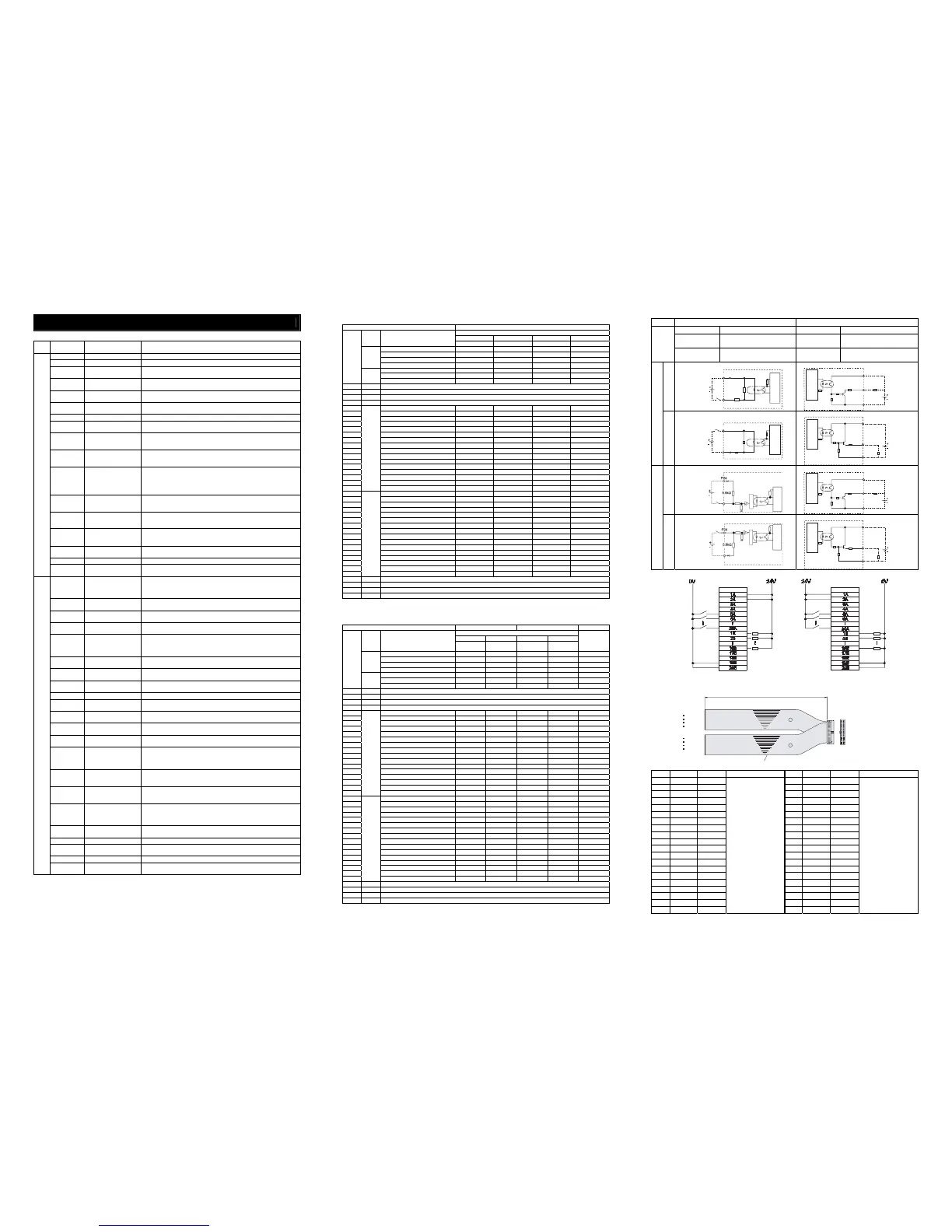
Signal Assignment for Each Mode
The signal assignment of I/O flat cable by the PIO pattern is as shown below. Follow the following table to connect the external equipment (such as PLC).
Corresponding Type All Types
Selection in Parameter No. 25 (PIO Pattern)
0 1 2 3
Category
PIO Functions
Positioning mode Teaching mode 256-point mode 512-point mode
Number of Positioning Points 64 points 64 points 256 points 512 points
Jog Signal × { × ×
Teaching Signal (Current Position Writing)
× { × ×
Input
Brake Release { × { {
Signal during Operation { { × ×
Zone Signal { × × ×
Pin No.
Output
Position Zone Signal { { { ×
1A 24V P24
2A 24V P24
3A − −
4A − −
5A IN0 PC1 PC1 PC1 PC1
6A IN1 PC2 PC2 PC2 PC2
7A IN2 PC4 PC4 PC4 PC4
8A IN3 PC8 PC8 PC8 PC8
9A IN4 PC16 PC16 PC16 PC16
10A IN5 PC32 PC32 PC32 PC32
11A IN6 − MODE PC64 PC64
12A IN7 − JISL PC128 P128
13A IN8 − JOG+ − PC256
14A IN9 BKRL JOG− BKRL BKRL
15A IN10 RMOD RMOD RMOD RMOD
16A IN11 HOME HOME HOME HOME
17A IN12 *STP *STP *STP *STP
18A IN13 CSTR CSTR/PWRT CSTR CSTR
19A IN14 RES RES RES RES
20A
Input
IN15 SON SON SON SON
1B OUT0 PM1 (ALM1) PM1 (ALM1) PM1 (ALM1) PM1 (ALM1)
2B OUT1 PM2 (ALM2) PM2 (ALM2) PM2 (ALM2) PM2 (ALM2)
3B OUT2 PM4 (ALM4) PM4 (ALM4) PM4 (ALM4) PM4 (ALM4)
4B OUT3 PM8 (ALM8) PM8 (ALM8) PM8 (ALM8) PM8 (ALM8)
5B OUT4 PM16 PM16 PM16 PM16
6B OUT5 PM32 PM32 PM32 PM32
7B OUT6 MOVE MOVE PM64 PM64
8B OUT7 ZONE1 MODES PM128 PM128
9B OUT8 PZONE/ZONE2 PZONE/ZONE1 PZONE/ZONE1 PM256
10B OUT9 RMDS RMDS RMDS RMDS
11B OUT10 HEND HEND HEND HEND
12B OUT11 PEND PEND/WEND PEND PEND
13B OUT12 SV SV SV SV
14B OUT13 *EMGS *EMGS *EMGS *EMGS
15B OUT14 *ALM *ALM *ALM *ALM
16B
Output
OUT15 *BALM
*BALM *BALM *BALM
17B − −
18B − −
19B 0V N
20B 0V N
(Note) “*” in codes above shows the signal of the active low.
PM1 to PM8 indicate the alarm binary code output signal when an alarm is generated.
(Reference) Signal of Active Low
Signal with “*” expresses the signal of active low. A signal of active low is a signal that the input signal is processed when it is
turned off, output signal is ordinary on while the power is on, and turns off when the signal is output.
Corresponding Type All Types CA Type All Types
Selection in Parameter No. 25 (PIO Pattern)
4 5 6 7
Category
PIO Functions
Electromagnetic
Valve Mode 1
Electromagnetic
Valve Mode 2
Force Control
Mode 1
Force Control
Mode 2
Pulse Train
Control Mode
Number of Positioning Points 7 points 3 points 32 points 5 points −
Jog Signal × × × × ×
Teaching Signal (Current Position Writing)
× × × × ×
Input
Brake Release { { { { {
Signal during Operation × × × × ×
Zone Signal { { × × {
Pin No.
Output
Position Zone Signal { { { { ×
1A 24V P24
2A 24V P24
3A − −
4A − −
5A IN0 ST0 ST0 PC1 ST0 SON
6A IN1 ST1 ST1 (JOG+) PC2 ST1 RES
7A IN2 ST2 ST2
*1
PC4 ST2 HOME
8A IN3 ST3 − PC8 ST3 TL
9A IN4 ST4 − PC16 ST4 CSTP
10A IN5 ST5 − − − DCLR
11A IN6 ST 6 − − − BKRL
12A IN7 − − − − RMOD
13A IN8 − − CLBR CLBR −
14A IN9 BKRL BKRL BKRL BKRL −
15A IN10 RMOD RMOD RMOD RMOD −
16A IN11 HOME − HOME HOME −
17A IN12 *STP − *STP *STP −
18A IN13 − − CSTR − −
19A IN14 RES RES RES RES −
20A
Input
IN15 SON SON SON SON −
1B OUT0 PE0 LS0 PM1(ALM1) PE0 PWR
2B OUT1 PE1 LS1(TRQS) PM2(ALM2) PE1 SV
3B OUT2 PE2 LS2
*1
PM4(ALM4) PE2 INP
4B OUT3 PE3 − PM8(ALM8) PE3 HEND
5B OUT4 PE4 − PM16 PE4 TLR
6B OUT5 PE5 − TRQS TRQS *ALM
7B OUT6 PE6 − LOAD LOAD *EMGS
8B OUT7 ZONE1 ZONE1 CEND CEND RMDS
9B OUT8
PZONE/ZONE2 PZONE/ZONE2 PZONE/ZONE1 PZONE/ZONE1
ALM1
10B OUT9 RMDS RMDS RMDS RMDS ALM2
11B OUT10 HEND HEND HEND HEND ALM4
12B OUT11 PEND − PEND PEND ALM8
13B OUT12 SV SV SV SV −/*ALML
*2
 Loading...


