INSTALLATION AND OPERATION INSTRUCTIONS
5-4
DC SERIES COMBI BOILERS DC 23-84, DC 29-106, DC 33-124, DC 33-160
5.2.5 Vent High-Limit
This sensor has been installed to ensure the boiler is shut down safely if the heat
exchanger or the venting system becomes blocked.
The Vent Hi-Limit is located at the bottom of the heat exchanger just to the left of
the vent outlet and above the condensate tray. For access, remove the vent stack
and the condensate tray.
5.2.6 Domestic Hot Water Flow Sensor
The DC series boilers are equipped with a ow sensor to measure water ow
through the domestic hot water circuit in the boiler. The minimum ow required to
activate the boiler is 0.5 GPM or 2 L/min.
• To service or replace the Water Flow Sensor:
• Disconnect power to the boiler
•
Turn off the Cold and Hot water valves below the boiler, release the water
pressure and drain the domestic hot water circuit. Leave the drain valves open.
• Disconnect the Molex connector at the sensor
• Remove the sensor by turning the nut counter clock wise. Take care not to
drain the water onto any of the electrical components.
• Clean or replace the ow sensor as required and reassemble in reverse order.
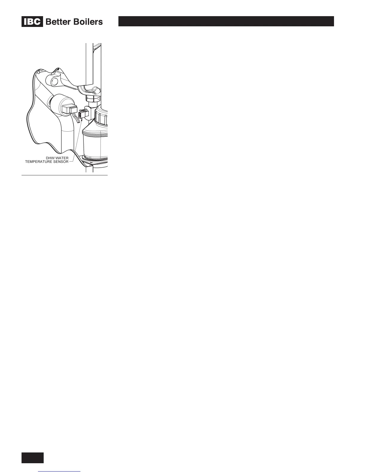
5.2.7 Domestic Hot Water Sensor
The DC Series boilers are equipped with a domestic hot water temperature sensor.
The sensor is located on the hot water outlet pipe and is just behind the boilers
condensate tray. For access, remove the vent stack and the condensate tray.
5.2.8 Outdoor Sensor
An Outdoor Sensor is supplied with each boiler. The sensor should be mounted
on the north side of the building away from any direct sunlight. The sensor must
also be kept away from any heat sources such as exhaust fan outlets, dryer
outlets, mechanical room ventilation grills etc.
The Outdoor Sensor is a 12KΩ sensor with resistance values as listed in Table
14. If the sensor is not connected to the boiler, the boiler will operate at the Boiler
Supply Temperature set in the User Set Up menu and operate as a Set Point
load.
DHW Temperature Sensor