READ
-IN
CYCLES
First
b
Second
90
180
270
90
180
270
Starwheel 2
R3
l5,
324, 325
R304
R309
~9
I
75-P4
P2-79
l75-P4
t-1
I
Key
Pressed
{_
r
I
,-
"A" Register Relay
l0-P3
P6-
l58
l0-P3
P6-
l58.
I I I
I'
I
I
"B" Register Relay
P5-86
f2-79
P5-86
1
Interposer
Magnet
Punch Clutch
180
Pl
180
Pl
Keyboard Restored
28
-P6-
158
28
-P6-
158
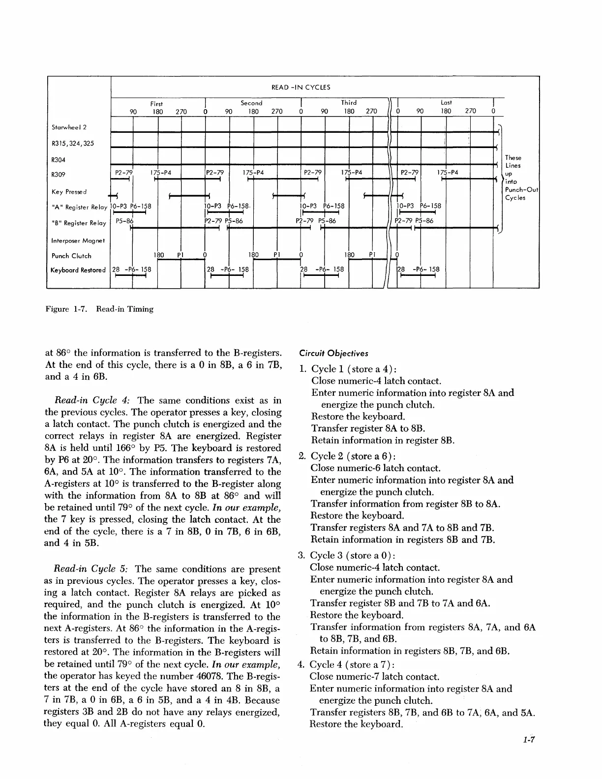
Figure
1-7.
Read-in
Timing
at
B6°
the
information is
transferred
to
the
B-registers.
At
the
end
of this cycle,
there
is a 0
in
BB,
a 6
in
7B,
and
a 4 in 6B.
Read-in Cycle
4:
The
same conditions exist as
in
the
previous cycles.
The
operator
presses a key, closing
a latch contact.
The
punch
clutch
is energized
and
the
correct relays in register
BA
are
energized. Register
BA
is
held
until 166°
by
P5.
The
keyboard
is restored
by
P6
at
20°.
The
information transfers to registers 7
A,
6A,
and
5A
at
10°.
The
information
transferred
to
the
A-registers
at
10° is transferred
to
the
B-register along
with
the
information from
BA
to
BB
at
B6°
and
will
be
retained until 79° of
the
next cycle.
In
our example,
the
7 key is pressed, closing
the
latch
contact. At
the
end
of
the
cycle,
there
is a 7
in
BB,
0
in
7B, 6
in
6B,
and
4 in 5B.
Read-in Cycle
5:
The
same conditions
are
present
as
in
previous cycles.
The
operator
presses a key, clos-
ing a latch contact. Register
BA
relays
are
picked
as
required,
and
the
punch
clutch
is energized.
At
10°
the
information in
the
B-registers is
transferred
to
the
next A-registers. At
B6°
the
information
in
the
A-regis-
ters is transferred to
the
B-registers.
The
keyboard
is
restored
at
20°.
The
information in
the
B-registers will
be
retained until 79° of
the
next cycle. In our example,
the operator has keyed
the
number
46078.
The
B-regis-
ters
at
the
end
of
the
cycle
have
stored
an
B
in
BB,
a
7 in 7B, a 0 in 6B, a 6 in 5B,
and
a 4
in
4B. Because
registers
3B
and
2B
do
not
have
any
relays energized,
they
equal
0.
All A-registers
equal
0.
1
Third
b
Last
T
0
90 180
270
90 180
270
0
,,
....,
I
i
-,
These
j
Lines
P2-79
l75-P4
P2-79
l75-P4
up
J
-~
>:into
I
L J
;
Punch-Out
I
l
Cycles
l0-P3
P6-l58
l0-P3
P6-l58
,,
I
I
,,
I
I
Pf-79
P5-86
f
PS-&
J
1
l,
180
Pl
~
1
28
-P6-
158
28
-P6-
158
r
Jl
Circuit Obiectives
1.
Cycle
1
(store
a
4)
:
Close numeric-4
latch
contact.
Enter
numeric
information into register
SA
and
energize
the
punch
clutch.
Restore
the
keyboard.
Transfer register
BA
to
BB.
Retain information
in
register
BB.
2.
Cycle 2
(store
a
6):
Close numeric-6
latch
contact.
Enter
numeric
information into register
BA
and
energize
the
punch
clutch.
Transfer
information from register
BB
to
BA.
Restore
the
keyboard.
Transfer registers
BA
and
7 A
to
BB
and
7B.
Retain information
in
registers
BB
and
7B.
3.
Cycle 3
(store
a
0):
Close numeric-4
latch
contact.
Enter
numeric information into register
BA
and
energize
the
punch
clutch.
Transfer
register
8B
and
7B to 7 A
and
6A.
Restore
the
keyboard.
Transfer
information from registers
BA,
7
A,
and
6A
to
BB,
7B,
and
6B.
Retain information in registers
BB,
7B,
and
6B.
4.
Cycle 4 ( store a
7)
:
Close numeric-7 latch contact.
Enter
numeric information into register
BA
and
energize
the
punch
clutch.
Transfer registers
BB,
7B,
and
6B to 7
A,
6A,
and
5A.
Restore
the
keyboard.
1-7