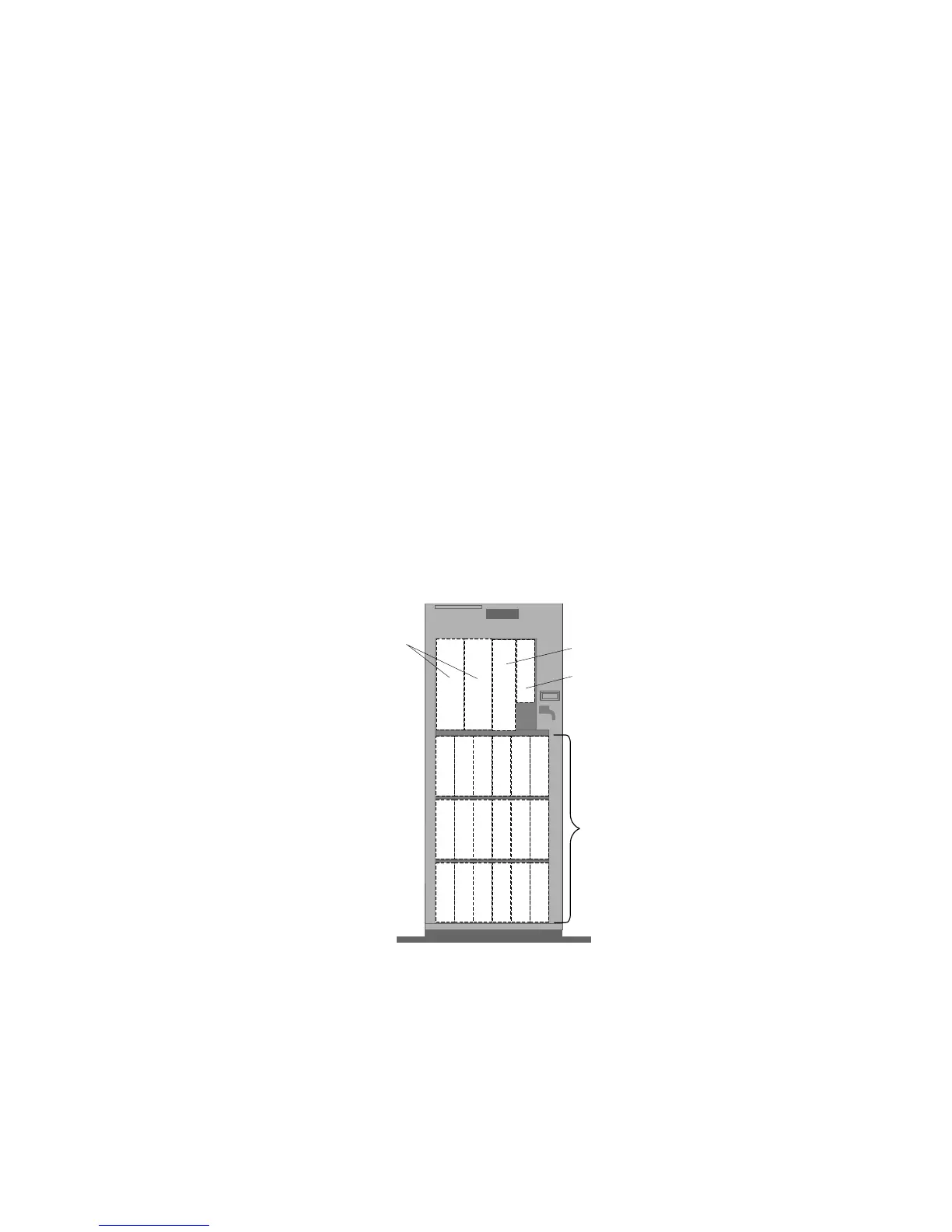
Installing Internal Drives
In a disk-array model, you can use the SCSI output connector
(daisy-chain connector) on the backplanes to serially link two
adjacent backplanes in banks C, D, and E. When you connect two
banks serially, each bank supports up to three half-high drives or six
slim-high drives. When backplanes are daisy chained, you can
control the hard disk drives in the banks with a single SCSI
connector on the ServeRAID adapter. This allows you to support
six half-high drives or 12 slim-high drives on a single SCSI-2 bus.
Note: The bank letter-designations are located on both vertical rails
on the front of the server. The bay-slot numbers are located
on the top of bank C and the bottom of bank E.
B1 B2
CD-ROM Drive (Bay A1)
Diskette Drive (Bay A2)
Open Bays
Bank C
Bays 1 - 6
Bank D
Bays 1 - 6
Bank E
Bays 1 - 6
Open Bays
A cover plate (sometimes called a bezel or face plate) covers the front
of bay B2 only. If you install a drive that uses removable media,
such as diskettes, optical discs, or tapes, you might have to change
this plate.
Chapter 5. Installing Options 199



 To Next Page