c. Store the side panels.
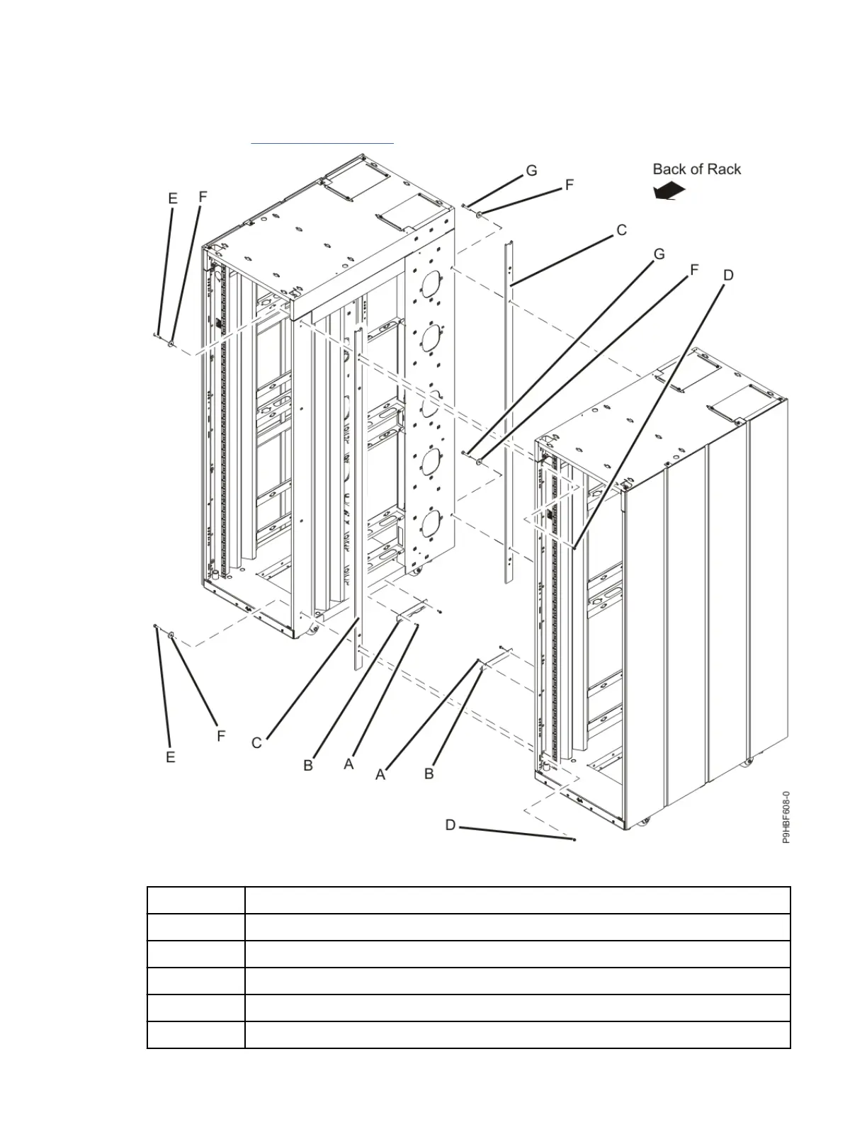
3. Remove the J-bracket screws (A) and bracket (B).
4. Use two screws (D) to install the spacer bracket (C, in front). Align and install the rear spacer bracket
(C), as shown in Figure 79 on page 113.
Figure 79. Removing the side panels, bracket, and standoffs to connect multiple racks
Item
Description
A Hex flange screw
B J bracket
C Spacer bracket
D M5 hex flange screws
E M8x35 screw
Racks and rack features 113
 Loading...