8. Temporarily restore the A feed -48V DC power to the PDP.
9. Check the A feed voltage for proper polarity. If the polarity is correct, proceed to the next step. If it is
not, correct the connections to obtain the proper voltage polarity and then continue with the next
step.
10. Verify that:
• A PWR LED on the front panel is green.
• B PWR LED on the front panel is red.
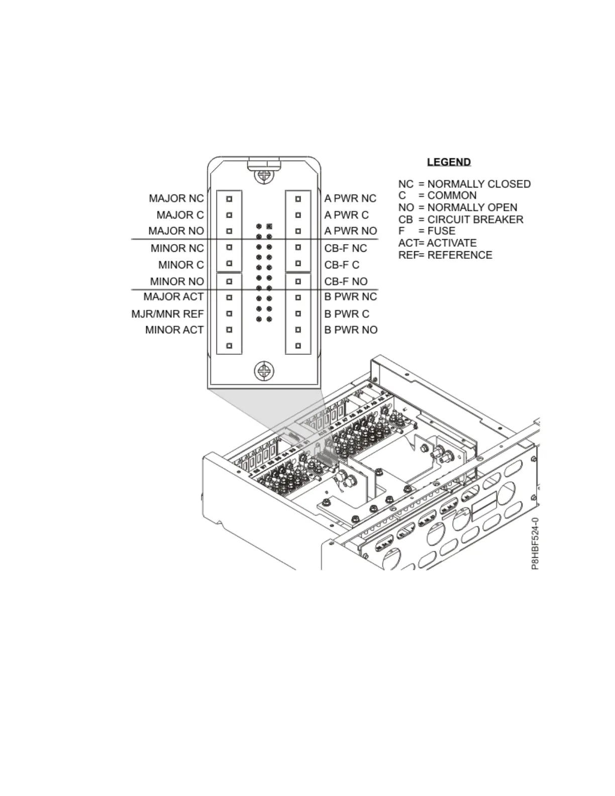
Figure 25. Alarm panel wiring connections
11. With A PWR LED green (normal operation) - but with B PWR LED red (off or failure operation) - test
the A PWR relay and contact alarm terminal.
• Ensure that there is continuity (0Ω) between Terminals C and NC.
• Ensure that there is an open circuit (∞Ω) between Terminals C and NO.
12. Temporarily restore the B feed -48V DC power to the PDP.
13. Check the B feed voltage for proper polarity. If the polarity is correct, proceed to the next step. If
polarity is incorrect, correct the connections to obtain the proper voltage polarity.
14. Verify the following:
• A PWR LED on the front panel is green.
• B PWR LED on the front panel is green.
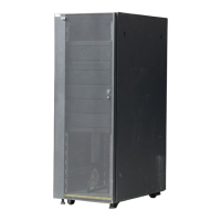
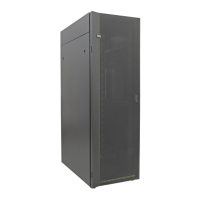
Racks and rack features
33
 Loading...